Table of Contents

Related Manuals for Lectrosonics UM450V


Summary of Contents for Lectrosonics UM450V
- Page 1 INSTRUCTION MANUAL UM450 Frequency-Agile UHF Belt-Pack Transmitter Featuring Digital Hybrid Wireless™ Technology (US Patent Pending) Fill in for your records: Serial Number: Purchase Date: Rio Rancho, NM, USA www.lectrosonics.com...
- Page 2 UM450 LECTROSONICS, INC.
- Page 3 1/4 wavelength flexible galvanized steel cable that connects to a 50 Ohm SMA port on the transmitter. Only the UM450 transmitter is covered in this manual. Companion receivers are covered in separate manuals. The UM450 will operate with any 400 Series Lectrosonics receiver and a variety of analog receivers in the same frequency group.
- Page 4 UM450 LECTROSONICS, INC.
-
Page 5: Table Of Contents
Frequency-Agile UHF Belt-Pack Transmitter Table of Contents General Technical Description ................................6 Introduction ......................................6 Digital Hybrid Technology ..................................6 UM450 Block Diagram ..................................6 No Pre-Emphasis/De-Emphasis ................................7 Pilot Tone Squelch ....................................7 Input Limiter ......................................7 Wide-Band Deviation .................................... 7 Long Battery life .................................... -
Page 6: General Technical Description
Because it uses an analog FM link, the Digital Hybrid enjoys all the benefits of conventional FM wireless The Lectrosonics Digital Hybrid system overcomes systems, such as excellent range, efficient use of RF channel noise in a dramatically new way, digitally spectrum, and long battery life. -
Page 7: No Pre-Emphasis/De-Emphasis
Frequency-Agile UHF Belt-Pack Transmitter The audio level LEDs indicate limiter activity. The first No Pre-Emphasis/De-Emphasis red LED indicates that the limiter is active and that the The signal to noise ratio of the 400 system is high transmitter is fully modulated (audio level is between +0 enough to preclude the need for conventional pre- and +10 dB). -
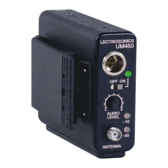
Page 8: Controls And Functions
(when using the recommended alkaline battery). The LED blinks red when there are only a few minutes Audio Level of life left. Used to adjust the audio input level for the proper modulation. LECTROSONICS, INC. -
Page 9: Modulation Leds
The circuitry is tightly packed into this unit. A longer screw will permanently damage the transmitter! Use • Once for 100 Series mode only Lectrosonics PN:28528 which is a Phillips head, • Two times for 200 Series mode 4-40 x 3/16", FL100 screw. -
Page 10: Battery Installation
9 Volt battery. It is important that you use ONLY All units with serial number 601 and up are capable of an ALKALINE or LITHIUM battery for longest life. Stan- working with Lectrosonics 400 Series Digital Hybrid dard zinc-carbon batteries marked “heavy-duty” or Wireless ™... -
Page 11: Attaching A Microphone And Adjusting Gain
Frequency-Agile UHF Belt-Pack Transmitter Attaching a Microphone and Adjusting Gain Adjusting the Transmitter Frequency 1) Ensure the battery is in good condition. If you are experiencing interference from another signal on your frequency, you may want to change the operat- 2) Insert the microphone plug into the input jack, ing frequency of your system. -
Page 12: Microphone Cord Termination
RF ground on VHF models and no other use is permitted. TA5F Connector Assembly Mic Cord Stripping Instructions NOTE: This termination is required on VHF transmitters and will still work fine on UHF transmitters. LECTROSONICS, INC. -
Page 13: 5-Pin Input Jack Wiring
15 of this instruction manual. Our service department can PIN 4 4K Ohm source load for non-Lectrosonics answer your questions regarding microphone compat- electret microphones. Use in conjunction with ibility. -
Page 14: Line Level Signals
Alternate locations for bypass capacitors CONNECTOR Leadless capacitors: P/N SCC330P All Lectrosonics lavaliere mics are already bypassed and do not need any additional capacitors installed for proper operation. Caution: When wiring the connector, do not use the connector body for any electrical connections. -
Page 15: Wiring Hookups For Different Sources
Frequency-Agile UHF Belt-Pack Transmitter Wiring Hookups for Different Sources SHIELD SHIELD BIAS AUDIO 2 WIRE ELECTRET MIC 3 WIRE ELECTRET MIC NEGATIVE BIAS AUDIO POSITIVE BIAS TA5F TA5F PLUG PLUG SLEEVE SHIELD SHIELD AUDIO AUDIO 2 WIRE ELECTRET MIC LINE LEVEL TA5F POSITIVE BIAS RCA or 1/4 "... -
Page 16: Replacement Parts And Accessories
Item Model/Part Number Replacement wire belt clip Lectrosonics #BCWire Replacment whip antenna Lectrosonics AMM (xx) - specify frequency block (xx) UHF Transmitter Antenna Specifications Measure the length of the whip that protrudes outside of the SMA connector to find the operating Frequency Block... -
Page 17: Troubleshooting
Frequency-Agile UHF Belt-Pack Transmitter Troubleshooting Before going through the following chart, be sure that you have a good battery in the transmitter. It is important that you follow these steps in the sequence listed. Symptom Possible Cause TRANSMITTER BATTERY LED OFF 1) Battery is inserted backwards. -
Page 18: Specifications And Features
This device complies with FCC radiation exposure limits as set forth for an uncontrolled environment. This device should be installed and operated so that its antenna(s) are not co-located or operating in conjunction with any other antenna or transmitter. LECTROSONICS, INC. -
Page 19: Service And Repair
There are no adjustments inside that will make a malfunctioning unit start working. LECTROSONICS’ Service Department is equipped and staffed to quickly repair your equipment. In warranty repairs are made at no charge in accordance with the terms of the warranty. Out-of-warranty repairs are charged at a modest flat rate plus parts and shipping. - Page 20 This warranty does not apply to used or demonstrator equipment. Should any defect develop, Lectrosonics, Inc. will, at our option, repair or replace any defective parts without charge for either parts or labor. If Lectrosonics, Inc. cannot correct the defect in your equipment, it will be replaced at no charge with a similar new item.