Advertisement
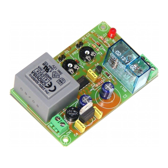
The I-111 circuit is a cyclic timer at 230 V AC with relay output. The module will maintain activated the output according to an
operating time and a quiescent time, both adjustable between 0,3 sec. and 1 min. Operating-Quiescent cycle is permanently
done until you disconnect the power supply. It includes an indicator timing led, connector to place an exterior potentiometer
and terminals to connect it.
Be carreful. Don't forget that there is 230 VAC in several parts of the circuit.
OPERATING
MODULE'S SUPPLYING :
mains connect this last one to the input terminal 230 VAC. Install a fuse and a switch as it is indicated in General Wiring
Map (see hereafter). Both are necessary to protect the module and for your own security, as it is indicated in EEC
regulations. Then, verify that you have correctly connected the module.
Before to connect the module to the mains inserting voltage, please do the rest of connections specified hereafter. Do not
forget that in several part of the module there is voltage (230 VAC), for this reason we suggest you to be carreful.
OPERATING-QUIESCENT CYCLE :
and quiescent time (when the relay will not be connected between two operating time).
To select operating and quiescent times you have to adjust potentiometers inserted in the P.C.B.
When the time is selected, press the push button to supply the module. The circuit I-111 will automatically connect the
output during the previously indicated operating time and the led will light. When the operating time will be finished, led and
output will be disconnected during the selected quiescent time. At the end of this quiescent time, the module I-110 will be
activated once again.
OUTPUT. CONNECTION OF THE LOAD
5 A. as maximum consumption. The relay has 3 output terminals the normally open at quiescent (NA), the normally closed at
quiescent (NC) and the common. The operating of this mechanism is the same as a switch with two (2) terminals NA and
common, if you wish that the output will be activated during the timer, or between the NC and the common, to obtain the
reverse operating. In the Output connection paragraph, you could appreciate the typical connection for a devices operating
at 12 VDC and to operate at 230 VAC. The installation is between the Common and NA, where the device or load that you
wish to control will be activated during the operating time. To obtain the inverse operating, substitute in the connection the
NA by
EXTERIOR INSTALLATION OF THE POTENTIOMETER :
P.C.B, you had to withdraw the soldering. Then, connect cables between jumpers indicated as "J1"and "J2" and new
potentiometers. These last potentiometers have to be lineal and offering 1M.
The Circuit I-111 had to be supplied by 230 VAC. Using an adequate plug and a cable for
The I-111 circuit has two times. Operating time (when the relay will be connected)
: The output Module (I-111) is controlled by a relay, allowing any load until
From 50 sec. Up to 30 min.
CYCLIC TIMER
TECHNICAL CHARACTERISTICS
Voltage. ........................................... 230 V. AC..
Medium Consumption. .................... 1 W.
Minimum Timing. ............................. 50 sec.
Maximum Timing. ........................... 30 min.
Maximum load at the relay. ............. 5 A.
Indicator timing Led. ........................ Yes.
you wish to substitute the potentiometer inserted in the
I-111
Advertisement
Table of Contents

Related Manuals for CEBEK I-111


Summary of Contents for CEBEK I-111
- Page 1 Indicator timing Led......Yes. The I-111 circuit is a cyclic timer at 230 V AC with relay output. The module will maintain activated the output according to an operating time and a quiescent time, both adjustable between 0,3 sec. and 1 min. Operating-Quiescent cycle is permanently done until you disconnect the power supply.
- Page 2 I-111 OUTPUT CONNECTION. LOAD. GENERAL WIRING MAP I-111...
Need help?
Do you have a question about the I-111 and is the answer not in the manual?
Questions and answers