
Related Manuals for EWS ES2030 SV


Summary of Contents for EWS ES2030 SV
- Page 1 ES2030 SV Control for ion exchangers and filter systems Instruction manual Software version 3.00...
-
Page 2: Table Of Contents
Contents Functional description........................…. Illustration .............................…. Service and regeneration displays …………................…. LED indicator lights…...………………………………………………………………..……………. LCD display………..…..………………………………………………………………..………… 3 First line…….…...……………………………………………………………………...………. Second line during service…….………………………………………………………...……. 3 Second line during regeneration………………………………………………………...……. 3 Displaying and altering program values............……………………..…. 4 Hardness of supply water / filter capacity..………………………………………………………..Current time………………………………...……………………………………………………….. - Page 3 “Flow pulse” output..…………………….…………..…………………………..……………...… 26 “Warning” output..…………………….…………..…………………………..………………...… 26 “Desalinate” output………………….…………..…………………………..…………………..… 27 Buzzer…….…………………………………………..…………………..………………………… 27 Programming mode.……...…………...…..……………………………..……………………….. 27 Examples of systems……................……………….…………… 28 Typical electrical wiring diagrams............……………….…………… 29 Wiring diagram ES2030 SV...............……………….…………… 31 Notes on installation and initial use............……………….…………… 32 Technical data….................……………………………....… 33 Declaration of conformity...........…………….………………….……...…… 34...
-
Page 4: Functional Description
ES2030 SV Functional description Functional description The controller ES2030 SV (wall mounted) is NOTE: For the sake of simplicity, in these used for the automatic control and monitoring instructions the treatment process carried out of single and double filter systems. -
Page 5: Illustration
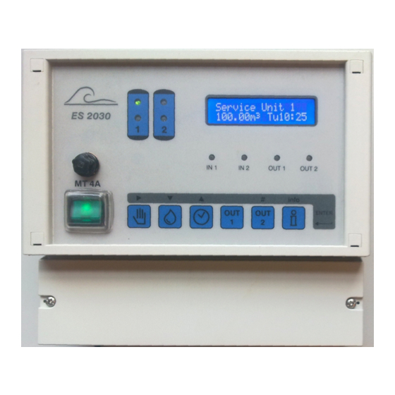
ES2030 SV Illustration Illustration Wall-mounted Service unit 1 100.00m3 Mo17:10 OUT1 OUT2 MT 4A info Enter Service filter 2 Main switch Output 2 16 Input 2 LED Service filter 1 Start regeneration Information 17 Output 2 LED Regeneration filter 1... -
Page 6: Service And Regeneration Displays
ES2030 SV Service and regeneration display Service and regeneration display LED control lamps Coloured control lamps show the unit’s major states : Filter 1 service (green) Filter 2 service (green) Filter 1 regeneration (orange) Filter 2 regeneration (orange) = Input 1 active... -
Page 7: Displaying And Altering Program Values
ES2030 SV Displaying and altering program values Displaying and altering program values The main program values can be displayed and altered if required by pressing a key. Example : Supply water hardness = 15 °D Diluted water 6 °D This gives an input value of : Hardness of supply water / 15 °D –... -
Page 8: Info Key
ES2030 SV Info Info key The information key is used to display various MinRg 4 information and values. Only the service If a “minimum regeneration distance” was telephone number can be changed using the selected during programming at step 8, the info key. -
Page 9: Water Delivery
ES2030 SV Info Water delivery to reflect new technology and customer requirements. Treated water The number of the version currently installed is displayed. 0.1m3 Programming the inputs The total quantity of water delivered by the IN1=Water meter system is shown. -
Page 10: Messages
ES2030 SV Messages Messages During service and during the regeneration of occurred as a result of a standstill hardening of the system, various signals are given the standby filter. The second filter is only depending on the type of controller and its regenerated if the relevant start signal is still programming. -
Page 11: Stopregeneration
ES2030 SV Messages / Cancel Buzzer / Switching OUT1 and OUT2 Stop regeneration Minimum regeneration distance S T A T U S S T A T U S Min.regen.period StopRegeneration This warning may have various causes Possible causes if activated by the water... -
Page 12: Initiating Regeneration Manually
ES2030 SV Initiating regeneration manually / Special functions Initiating regeneration manually A regeneration cycle can be initiated manually - If the time function for ‘delayed regeneration’ at any time pressing the ‘Start’ key with the has already been activated (and the time symbol . -
Page 13: Switching From Parallel To Alternate
ES2030 SV Special functions Switching from parallel to alternate In single filter system, the service filter will be regenerated after 4 seconds without initialisation and without recalculation of the filter capacity. If parallel switching was selected when programming filter switching at program step In two filter systems the standby filter will be 1.4 then it is possible to switch over to... -
Page 14: Displaying And Modification Of The Basic Settings
ES2030 SV Display and modification of the basic settings Display and modification of the basic settings General information on programming and language selection On first use, the controller is adjusted to the After 4 seconds this changes to: operating data of the water treatment system Start by entering basic settings. -
Page 15: Filter Switching
ES2030 SV Display and modification of the basic settings 1. Filter switching Start Single filter 1 Step no.: SingleFilter1Y/N If you enter ‘YES’ the system consists of 1 filter. Single filter 2 Step no.: SingleFilter2Y/N If you enter ‘YES’ the system consists of 1 filter. - Page 16 ES2030 SV Display and modification of the basic settings Series switching Step no.: Series connecY/N Select series switching when the filters in a two filter system were set up in series. For example: single flow partial desalination system with an H exchanger and a Na exchanger.
-
Page 17: Electrical Control
ES2030 SV Display and modification of the basic settings 2. Electrical control The controller can be expanded with this relay by fitting the IF expansion card (connector: OUT1 and connector OUT2). ATTENTION: This program step can only be selected if the controller is fitted with the IF2030 expansion card. -
Page 18: Number Of Regeneration Switch Phases
ES2030 SV Display and modification of the basic settings 3. Number of regeneration switch phases 1.* / 2 Step no.: Stage Stages Enter the number of regeneration switch phases for individual valve control. (max. 9 phases). 4. Single valve control This program step determines what valves are opened in what phase. -
Page 19: Regeneration Times
ES2030 SV Display and modification of the basic settings 5. Regeneration times Step no.: Time phase Time phase1: 10m The number of regeneration switch phases for individual valve control was set at program step 3.1. At this program step, enter the required times for each of the periods according to the number of regeneration phases. -
Page 20: Delayed Regeneration
ES2030 SV Display and modification of the basic settings 6. Delayed regeneration Step no.: Time Delayed Y/N A regeneration can be initiated at any time during the day. But it is often desirable not to have a regeneration during production times, since for instance the water pressure then may be insufficient for regeneration. -
Page 21: Starting On Real Time Clock
ES2030 SV Display and modification of the basic settings Starting on real time clock Step no.: Timestart A regeneration can be started depending on the real time clock. There is the possibility for programming two starting times at one day. -
Page 22: Minimum Regeneration Distance
ES2030 SV Display and modification of the basic settings 7.1 / 7.2 8. Minimum regeneration distance Step no.: Min.reg.time Y/N The minimum distance between two regenerations in ion exchangers can be calculated and monitored on the basis of the system’s capacity and the maximum water demand. -
Page 23: Definition Of Input Functions
ES2030 SV Display and modification of the basic settings 9. Definition of input functions The controller is provided as standard with one input for one input function (connection IN1). If the IF expansion card is added, the controller is expanded with a second input for a further input function (connection IN2). -
Page 24: Water Meter" Input
ES2030 SV Display and modification of the basic settings 10. ‘Water meter’ input The flow rate of the treated water is established using a pulse water meter, and when a preset amount has been delivered a regeneration is initiated. The amount of water remaining before the next regeneration is shown in the LCD display. -
Page 25: Filter Capacity
ES2030 SV Display and modification of the basic settings Filter capacity 10.3 Step no.: 10.4 Capacity 1800 10.4 Capacity ION exchanger The physical unit of the filter capacity depends on the unit of supply water hardness selected at step 10.3. It gives the soft water amount in m... -
Page 26: 12 "Start Regeneration" Input
ES2030 SV Display and modification of the basic settings 12. ‘Start’ input This input can be used to start a regeneration of the currently operating filter externally with a key or a water analysis device. In alternate filter service the standby filter is put into service. -
Page 27: Definition Of Output Functions
ES2030 SV Display and modification of the basic settings 15. Definition of output functions The controller is not equipped with the necessary additional relay for output functions as standard. The controller can be expanded with this relay by fitting the IF expansion card (connector: OUT1 and connector OUT2). -
Page 28: Additional Program" Output
ES2030 SV Display and modification of the basic settings 16. ‘Additional program’ output An additional relay can be controlled during the regeneration of a filter. This can be used to initiate washing programs or switch on supply or dosage pumps. In the following steps the switch on point is set before, during or after regeneration, and the time the relay stays switched on is determined. -
Page 29: Flow Pulse" Output
ES2030 SV Display and modification of the basic settings 18. ‘Flow pulse’ output 15.* / 16.* 18.1 Step no.: 18.1 imp.succes 100l Litres If the flow pulse function is selected, the relevant additional relay is activated after a set amount of water. Values from 1 to 9999 litres can be entered. The next program step determines how long the relay remains active for each pulse. -
Page 30: 20 "Desalinate" Output
ES2030 SV Display and modification of the basic settings 20. ‘Flushing’ output The ‘flushing’ function can be used to control a volume proportionate flushing or clarification. The flushing time determines how long the flushing valve remains 15.* -19.* open during a flushing process. The flushing interval sets the amount of flow after which the flushing valve is opened. -
Page 31: Examples Of Systems
ES2030 SV Examples of systems Examples of systems V2 V3 V5 V6 Input 1 Double sand filter with individual valves. -
Page 32: Typical Electrical Wiring Diagrams
ES2030 SV Typical electric wiring diagrams Typical electrical wiring diagrams Connecting a magnetic valve opening under voltage to : Connector V1 : terminals 5 and 7 Connector V2 : terminals 8 and 10 Connector V3 : terminals 11 and 12... - Page 33 ES2030 SV Typical electric wiring diagrams Connection to a signal lamp, klaxon or magnetic valve active when voltage applied on potential free relay output : NO NC Connector OUT1 : terminals 3 and 28 bridge from 4 to 27 Connector OUT2 : terminals 3 and 31...
-
Page 34: Wiring Diagram Es2030 Sv
ES2030 SV Wiring diagram... -
Page 35: Notes On Installation And Initial Use
ES2030 SV Notes on installation and initial use Notes on installation and initial use General Installation and commissioning of the control system may only be carried out by trained specialists who are familiar with these operating instructions and the applicable regulations on safe working practices and accident prevention. -
Page 36: Technical Data
ES2030 SV Technical data Technical data Electrical supply : + 10% 50-60 Hz fuse 4A mT 115V + 10% 50-60 Hz fuse 4A mT 230V + 10% 50-60 Hz fuse 4A mT 115/24V + 10% 50-60 Hz fuse 4A mT... -
Page 37: Declaration Of Conformity
: EN 61000-6-3, EN55022 Immunity standard : EN 61000-6-1 Low voltage directive : 2006/95/EG Report Report number : EWS / EMC / ES2030SI This declaration was issued by : Date : 11 – 03 - 2020 Name : V. Naeber... - Page 38 EWS). All the costs which exceed the obligations of EWS under this Warranty, such as, but not limited to, travel and accommodation costs and costs for assembly and dismantling are for the account and risk of the customer.
- Page 39 Except where such limitations and exclusions are specifically prohibited by applicable law EWS shall not be liable for: Damage to other property caused by defects in the EWS product, damages based upon inconvenience, loss of use of the product, loss of time, commercial loss or: Any damages, whether incidental, [consequential or otherwise] special, indirect or consequential damages, injury to persons or property, or any other loss.
Need help?
Do you have a question about the ES2030 SV and is the answer not in the manual?
Questions and answers