
Related Manuals for EWS UFS8000


Summary of Contents for EWS UFS8000
- Page 1 UFS8000 Controller for ultra filtration plants Operating manual Software version 1.06...
-
Page 2: Table Of Contents
Contents 1. System description ........................... 1 1.1. General ............................1 1.2. Functionality overview ......................... 1 1.3. Diagram of the unit ........................2 1.4. Unit configuration ........................2 1.5. Description of the unit ........................2 2. Picture of front side ........................... 4 3. - Page 3 6.7.1. Flow Feed .......................... 31 6.7.2. Flow Permeate 1 ....................... 31 6.7.3. Flow Permeate 2 ....................... 31 6.7.4. Flow Backwash ......................... 31 6.7.5. Flow meter settings ......................32 6.7.6. Properties flow meter ......................32 6.7.7. Monitoring minimum flow ....................33 6.7.8.
- Page 4 9.2. Integrity test ..........................57 9.3. Standby ............................. 57 9.4. Pre Flush ........................... 58 9.5. Filtration ............................. 58 9.6. Backwash ..........................59 9.7. CEB ............................59 10. Retrieve information ........................60 10.1. General ............................ 60 10.2. Service number ........................60 10.3.
- Page 5 16.1.1. Switch on / off e-mail function ..................78 16.1.2. IP address of SMTP server ..................... 78 16.1.3. E-mail sender ........................78 16.1.4. E-mail address of the recipient ..................79 16.2. Log functions ........................... 79 16.2.1. Alarm log function ......................79 17.
- Page 6 23.6.5. Back light ......................... 98 23.6.6. Media ..........................99 24. Security ............................100 24.1. Controller ..........................100 24.1.1. Pass word ........................100 24.1.2. Menu ..........................101 24.1.3. Process ......................... 101 24.2. Internet ..........................101 25. Power failure ..........................102 25.1. Clock ............................102 25.2.
- Page 7 40. Warranty conditions ........................122...
-
Page 8: System Description
System description 1. System description 1.1. General The UFS8000 is applicable for the automatic control and monitoring of ultra filtration units. Thanks to the flexible programmable software this controller is suitable for a large number of various water treatment applications. -
Page 9: Diagram Of The Unit
UFS8000 System description 1.3. Diagram of the unit The unit is schematically represented in the following diagram The diagram features all the components defined in the controller. Only the components that are connected to the available in- and outputs can be displayed. - Page 10 UFS8000 System description The controller is routinely delivered in the “Standby Stop" phase. The unit will not be automatically started until this is switched on manually (see § 9.1 “Standby stop” on page 57. Once it is switched on, the controller will no longer start in this phase after a power failure, unless this phase is activated via the programming (see §...
-
Page 11: Picture Of Front Side
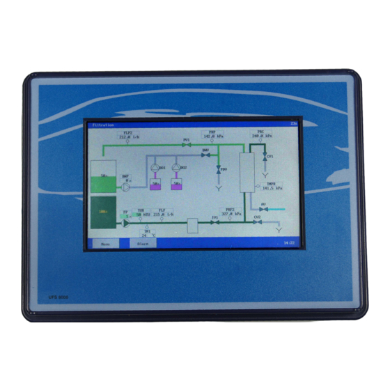
UFS8000 Picture of front side 2. Picture of front side 1 LCD display + touch panel... -
Page 12: Measurement And Function Display
UFS8000 Measurement and function display 3. Measurement and function display 3.1. LCD display The LCD display features further information about the active process. Picture 3.1 The top bar displays the process the unit is in. Also shown are the measurement values or statuses of the connected components. - Page 13 UFS8000 Measurement and function display Positions of the inputs: The (digital) inputs can have the following statuses: The input function is not supervised (grey). The input function is supervised and inactive (green). The input function is supervised and active, but the time delay is not finished yet (yellow).
- Page 14 UFS8000 Measurement and function display Situation of the tank The tanks can be displayed with different background colours. These colours have the following meanings: Raw water tank Permeate tank Chemical tank If the tank is equipped with level measuring (0(4)-20mA), the level will be indicated per ratio.
-
Page 15: General Operation
UFS8000 General operation 4. General operation A touch panel is used for the operation and programming of this controller. Details are provided below about the general arrangement of the screen, the meaning of the various “keys” and the general display /input windows. -
Page 16: Window
UFS8000 General operation 4.3. Window The various settings can be made in windows. The different types of settings are: values, texts and dropdown lists. 4.3.1. Set value or text The box with the required settings has to be selected to change a value or text and calling up a new window where the value / text can be changed. -
Page 17: Confirmation
UFS8000 General operation Confirming the choice calls up another window for the final confirmation. Confirm the choice again. Cancel the choice. The changed setting is stored in the memory after you quit the main menu. 4.3.4. Confirmation In some cases confirmation is required subsequent to a choice or change. The key can be used to confirm the choice or change. -
Page 18: Unit Configuration
UFS8000 Configure unit 5. Unit Configuration This chapter describes how the unit may be configured. The unit configuration option is featured in the main menu. If the unit configuration is selected you will be asked if the unit may be placed in Standby. -
Page 19: Inventory
UFS8000 Configure unit 5.1. Inventory Before the components and process phases can be programmed, an inventory has to be made of the components with the corresponding properties. Selecting the item “Inventory” calls up a list of potential components that may be connected. If a specific component from the list is connected to the controller the component's corresponding window can indicate which pins the component is connected to. -
Page 20: Security Switch
UFS8000 Configure unit If a component is not connected, then the “----“ option should be chosen. This disconnects hardware and software. Component Hardware Software The component will then no longer be listed in the remaining settings, unless the component was connected to another component in the settings for that other component. -
Page 21: Analogue Control
UFS8000 Configure unit 5.1.2. Analogue control Certain components can be controlled via an analogue output (such as a pump via a frequency regulator). An analogue output can be selected for these components. In the settings of the processes (see § 5.2.2 “Units (phases)” on page 16) it can subsequently be set to any percentage of the current range (0-20mA or 4-20mA);... -
Page 22: Programming
UFS8000 Configure unit 5.2. Programming Subsequent to the inventory of the components and entering the specific properties of the components, you may enter other properties in the component programming and the various phases of the UF unit can be set. -
Page 23: Units (Phases)
UFS8000 Configure unit 5.2.2. Units (phases) Once the components have been inventoried and programmed the various process phases of the RO unit may be programmed. Only the programmable phases will be displayed. During a “time” phase the time is entered (0-999) in seconds or minutes. If a time of 0 is entered the corresponding phase is omitted. -
Page 24: Components
UFS8000 Components 6. Components An examination is made in this chapter of the inventory and programming options for the various components that have to be connected. This component may divided into: Valves Pumps Alarm Switches Storage tank Other Where a reference is made in this chapter to inventory, this means the window located via the “Installation –... -
Page 25: Concentrate Valves
UFS8000 Components 6.1.3. Concentrate valves In the case of the “Concentrate valve” all that has to be entered, in the inventory, is the relay output it is connected to. A security switch can be activated. This can be linked to one if the available inputs, and it can be set if the switch is “normally closed”... -
Page 26: Permeate Dump Valve
UFS8000 Components 6.1.6. Permeate dump valve In the case of the “Permeate dump valve” all that has to be entered, in the inventory, is the relay output it is connected to. A security switch can be activated. This can be linked to one if the available inputs, and it can be set if the switch is “normally closed”... -
Page 27: Backwash Pump
UFS8000 Components 6.2.2. Backwash pump In the case of the “Backwash pump” all that has to be entered, in the inventory, is the relay output it is connected to. A security switch can be activated. This can be linked to one if the available inputs, and it can be set if the switch is “normally closed”... - Page 28 UFS8000 Components Attention! If the dosing pump is activated in successive phases (such as phase 1 to phase 2 or from the “Filtration” phase to the “Backwash” phase), the switch-on delay and dosing time will not be reset during the start of next phase.
-
Page 29: Alarm
UFS8000 Components 6.3. Alarm An alarm output may be connected only to a relay output function (OUTx). Activation of the relay is completely independent of the phase the unit is in. In the case of the “Alarm output” all that has to be entered, in the inventory, is the relay output it is connected to. -
Page 30: Switches
UFS8000 Components 6.4. Switches Switches (e.g. level switches) may be connected only to the digital inputs (IN1 to IN8) (IN9 - IN16, when circuit board cb-8in (1) present, IN17 - IN24, when circuit board cb-8in (2) present). Furthermore, a number of switches can be determined, for each process step. -
Page 31: Stop
UFS8000 Components 6.4.2. Stop The “Stop” switch function may be used for various purposes. The programming can be set to show if the unit has to be switched on automatically or manually, when the malfunction has been remedied. For information about the inventory see § 6.4 “Switches”... -
Page 32: Start Backwash
UFS8000 Components 6.4.4. Start backwash The “Start backwash” switch can be used to start a backwash. For information about the inventory see § 6.4 “Switches” on page 23. A further delay can be entered (0-9999 seconds) for monitoring. 6.4.5. Alarm reset The “Alarm reset”... -
Page 33: Tanks
UFS8000 Components 6.5. Tanks 6.5.1. Clean water tank There are two available types of level measuring, namely measurements with level switches (1 or 2) or level measurements with a 0(4)-20mA output that can be connected to a 0-20mA control input (if available). -
Page 34: Raw Water Tank
UFS8000 Components As far as level measuring is concerned, the percentage with empty tank, the percentage with full tank and the percentage for refilling the tank can be specified. The installation will enter the “Filtration” phase as soon as the percentage goes below the level of the one specified for filling the tank. -
Page 35: Dosing Tank
UFS8000 Components If only a low-level switch is programmed, the raw water tank programming can be used to set a delay before the unit is switched on in the “Filtration” phase. If the low-level switch is active the unit will move directly out of the “Filtration”... - Page 36 UFS8000 Components You can secure the low-level switch by entering a delay of 0-9999 seconds. Also, it is possible to indicate whether the unit must be switched off when the level in the dosing tank is too low. When the unit is turned off, you can have the unit turn on automatically when the dosing tank is filled up to a sufficient level.
-
Page 37: Recorder Outputs
UFS8000 Components 6.6. Recorder outputs Through optional prints (ca-3rec), three or six recorder outputs (0-20mA) can be added. If the print is connected, then the recorder functions will be displayed in the inventory list.(Recorder 1,2,3,4,5 and 6) Each output can be set separately within a range of 0-20mA or 4-20mA. Which signals are to be transmitted at the output concerned can be specified next. -
Page 38: Flow Meter
UFS8000 Components 6.7. Flow meter The flow meters equipped with a 0(4)-20mA output can be connected to the control panel. It is possible to specify thresholds for the upper and lower limits, both with a programmable time delay. It is also possible to specify whether the installation should be shut down in case of either positive or negative crossing of the specified values. -
Page 39: Flow Meter Settings
UFS8000 Components 6.7.5. Flow meter settings This description cites the properties of flow measurement in the feed water as an example. Similar properties apply for other flow measurements. The 0-20mA input that is connected to the concerned flow meter can be selected for the inventarisation. -
Page 40: Monitoring Minimum Flow
UFS8000 Components 6.7.7. Monitoring minimum flow For monitoring purposes the minimum limit of 0,1 to 10.000,0 can be entered. A delay can also entered (1-9999 sec). During the delay the measured value has to be under the limit so an alarm is given if the unit is switched off. -
Page 41: Pressure Meter
UFS8000 Components 6.8. Pressure meter The pressure meters equipped with a 0(4)-20mA output can be connected to the control panel. It is possible to specify thresholds for the upper and lower limits, both with a programmable time delay. It is also possible to specify whether the installation should be shut down in case of either positive or negative crossing of the specified values. -
Page 42: Pressure Meter Settings
UFS8000 Components 6.8.7. Pressure meter settings This description cites the properties of pressure measurement in the feed water as an example. Similar properties apply for other pressure measurements. The 0-20mA input that is connected to the concerned pressure meter can be selected for the inventarisation. -
Page 43: Monitoring Minimum Pressure
UFS8000 Components 6.8.9. Monitoring minimum pressure For monitoring purposes the minimum limit of 0.1 to 10.000,0 can be entered. A delay can also entered (1-9999 sec). During the delay the measured value has to be under the limit so an alarm is given if the unit is switched off. -
Page 44: Turbidity Meter
UFS8000 Components 6.9. Turbidity meter A turbidity meter equipped with a 0(4)-20mA output can be connected to the control panel. It is possible to specify thresholds for the upper and lower limits, both with a programmable time delay. It is also possible to specify whether the installation should be shut down in case of either positive or negative crossing of the specified values. -
Page 45: Monitoring Minimum Turbidity
UFS8000 Components 6.9.3. Monitoring minimum turbidity For monitoring purposes the minimum limit of 1 to 2.500 NTU can be entered. A delay can also entered (1-9999 sec). During the delay the measured value has to be under the limit so an alarm is given if the unit is switched off. -
Page 46: Temperature
UFS8000 Components 6.10. Temperature A temperature meter equipped with a 0(4)-20mA output can be connected to the control panel. It is possible to specify thresholds for the upper and lower limits, both with a programmable time delay. It is also possible to specify whether the installation should be shut down in case of either positive or negative crossing of the specified values. -
Page 47: Monitoring Minimum Temperature
UFS8000 Components 6.10.3. Monitoring minimum temperature For monitoring purposes the minimum limit of 1 to 200 can be entered. A delay can also entered (1-9999 sec). During the delay the measured value has to be under the limit so an alarm is given if the unit is switched off. -
Page 48: Transmembrane Pressure
UFS8000 Components 6.11. Transmembrane pressure The transmembrane pressure can be determined in the controls. This is determined according to the formula: Transmembrane pressure = ((“Pressure Feed 2” + “Pressure Concentrate”) / 2) – “Permeate Pressure”. It is possible to specify thresholds for the upper and lower limits, both with a programmable time delay. -
Page 49: Monitoring Minimum Transmembrane Pressure
UFS8000 Components 6.11.2. Monitoring minimum transmembrane pressure For monitoring purposes the minimum limit of 0,1 to 1000,0 can be entered. A delay can also entered (1-9999 sec). During the delay the measured value has to be under the limit so an alarm is given if the unit is switched off. -
Page 50: Ph Meter
UFS8000 Components 6.12. pH meter The pH meters equipped with a 0(4)-20mA output can be connected to the control panel. It is possible to specify thresholds for the upper and lower limits, both with a programmable time delay. It is also possible to specify whether the installation should be shut down in case of either positive or negative crossing of the specified values. -
Page 51: Monitoring Minimum Ph
UFS8000 Components 6.12.3. Monitoring minimum pH For monitoring purposes the minimum limit of 0,1 to 14,0 can be entered. A delay can also entered (1-9999 sec). During the delay the measured value has to be under the limit so an alarm is given if the unit is switched off. -
Page 52: Uf Unit
UFS8000 UF Unit 7. UF Unit This chapter will examine the various phases of the UF unit. The manual control opportunities are explained in § 9 “Manual operation of the unit” on page 57. 7.1. Properties The general characteristics with regards to the installation can be set in this window. -
Page 53: Filtration
UFS8000 UF Unit 7.2. Filtration During the "Filtration" phase the unit provides treated water: the untreated water generally flows via via the feed pump to the inlet valve and then to the ultra filtration module. The production of treated water can be launched depending on the level of water in the raw water en clean water tank, depending on the position of the “Filtration start”... -
Page 54: Pre Flush
UFS8000 UF Unit If no 2 backwash is desired, the phase may be omitted by turning the phase switch off (no check mark in “Activate”). If the phase is activated the various stages can be programmed. 7.4. Pre Flush The "Pre Flush" phase is used to clean the membrane before going into “Filtration”. - Page 55 UFS8000 UF Unit The name of the sub-process can be set. This is because the order of the sub-processes for this phase is not always identical for every installation. For each step you can enter which inputs of limits are monitored, which outputs have to be activated and the time duration of the phase (0-9999 seconds / minutes).
-
Page 56: Ceb 1
UFS8000 UF Unit 7.7. CEB 1 The “CEB 1” phase is used to clean the membrane chemically at adjustable intervals. The backwash may comprise a max. of 11 stages each with a time duration of 0-9999 seconds /minutes. If no backwash is desired, the phase may be omitted by turning the phase switch off (no check mark in “Activate”). -
Page 57: Ceb 2
UFS8000 UF Unit 7.8. CEB 2 The “CEB 2” phase is used to clean the membrane chemically at adjustable intervals. The backwash may comprise a max. of 11 stages each with a time duration of 0-9999 seconds /minutes. This phase can be set in the same way as the “CEB 1” phase, with the difference, however, that instead of the interval start based on the number of backwashes, it can be opted for an interval start based on the number of executed “CEB 1”... -
Page 58: Integrity Test
UFS8000 UF Unit 7.10. Integrity test The “Integrity test” phase can only be switched on and off manually in the “Standby” phase to check the membrane for any leakages. A “rest” stage will first of all be switched on. The actual test can subsequently be started and stopped via manual control. -
Page 59: Standby
UFS8000 UF Unit It can be indicated in the "Properties” window which pressure is to be measured during the test. Furthermore, the permissible decrease in the measured pressure (per minute) can be entered. The selected pressure gauge and the decrease will be displayed during the test period. -
Page 60: Standby Stop
UFS8000 UF Unit 7.12. Standby Stop The controller is routinely delivered in the “Standby Stop” phase. The unit will not start up automatically until this is manually switched on (see § 9.1 “Standby stop” on page 57). Once it is switched on, subsequent to a power failure the controller will no longer start up in this phase, unless this is activated via the programming prior to the power failure. -
Page 61: Alarms
UFS8000 Alarms 8. Alarms The controller features various monitorings of both the operation of the RO unit and the operation of other functions in the controller (such as the SD card function ). 8.1. General overview The alarms can be recorded via an SD card, via e-mail or via an RS232 or RS485 connection. - Page 62 UFS8000 Alarms An alarm, in the alarm window takes the following form: The window provides the following information: - line 1 : x/y x = number of the warning, y = number of warnings - line 2 : brief description of the alarm situation given.
-
Page 63: Overview Alarms
UFS8000 Alarms 8.3. Overview alarms Shortened display Description Backup settings The last programming changes are not stored. The previous programming is loaded. Check the parameters or load an back-up through a SD Card. Default settings The configuration files on the hard disk are disabled or unavailable The controller has to be configured again or a back-up loaded. -
Page 64: Manual Operation Of The Unit
UFS8000 Manual operation of the unit 9. Manual operation of the unit The unit can be controlled manually. The main menu's “Manual control” features an overview of the manual operations possible at that time. The options for each phase are shown below. -
Page 65: Pre Flush
UFS8000 Manual operation of the unit - Starting the Backwash” phase via “Backwash” The backwash phase is started. If two backwash phases have been activated, then the backwash phase whose turn it is will be started. See § 7.6 “Backwash 2” on page 48. -
Page 66: Backwash
UFS8000 Manual operation of the unit 9.6. Backwash Several actions can be carried out during the “Backwash 1” and “Backwash 2” phases (if enabled). - Stopping of the backwash via “Stop Backwash” The backwash is interrupted and the next phase, whose turn it is, is started. -
Page 67: Retrieve Information
UFS8000 Information and history 10. Retrieve information Various types of data can be retrieved from the information menu, such as: the Software version, the service telephone number, the number of service hours, the status of the inputs and outputs, the alarm history, the maintenance interval (if programmed). -
Page 68: Outputs
UFS8000 Information and history 10.4. Outputs The window shows the status of the relay outputs. A line is established as follows: <number > <description > <status> <number > : indication of relay output on the print (1=”OUT 1”) <description > : brief description of the function <status>... -
Page 69: Ceb 2
UFS8000 Information and history 10.7. CEB 2 See § 10.6 “CEB 1” on page 61. 10.8. CEB 3 See § 10.6 “CEB 1” on page 61. 10.9. Alarm history The window gives an overview of the last 20 changes in alarm situations. -
Page 70: E-Mail
UFS8000 Information and history 10.11. E-mail It is possible in the controller to send an e-mail in the event of a specific (alarm) situation or when the situation is removed. An e-mail can be sent switched on or switched off (see §... -
Page 71: Outputs 0-20Ma
UFS8000 Information and history 10.14. Outputs 0-20mA The currently transmitted current can be read on a recorder in this window. This option is only available if the corresponding optional print ca-3rec is present. If no window function is connected, then no text will be displayed and no current will be transmitted. -
Page 72: Print Composition In The Controller
UFS8000 Information and history 10.16. Print composition in the controller The controller comprises multiple PCBs (Printed circuit board). The window shows what PCBs the controller consists of. This allows you to check if the PCBs are also actually being detected by the software. -
Page 73: User Settings
UFS8000 User settings 11. User settings 11.1. LCD Display The control unit has lighting in the LCD Display. In this window you can specify the brightness of the lightning. Furthermore you can specify in this window whether the lighting should be dimmed or switched off (=0%) when the touch panel is not used for longer than a certain period of time. -
Page 74: Clock
UFS8000 Clock 12. Clock 12.1. General The time and date can be set in the controller. The time and date are used in various functions, such as data “logging”. The clock setting option is located in the main menu. The controller has a battery so the time and date can be kept. If the controller is switched on again the time and date have to be reset. -
Page 75: Language Setting
UFS8000 Clock / language setting The changed date is directly up-to-date. The data format will also apply directly. However, this is not stored when you quit the main menu. The control unit also checks whether the date is correct (year> 2009). -
Page 76: Ethernet
UFS8000 Ethernet 14. Ethernet Attention ! This chapter only applies to control unit type UFS8x1x-xxxx. The controller is suitable for communicating via Ethernet. The web server on the controller allows information to be exchanged with the controller via a web browser (such as Internet Explorer) (see also §... -
Page 77: Subnetmask
UFS8000 Ethernet 14.1.3. Subnetmask In the window the subnetmasker is entered after “NM”. This generally has to be set as 255.255.255.0, showing that the first 3 numbers of an IPaddress, within the network, have to be the same and the final number has to be unique. - Page 78 Figure 14.1 Examples: 1) If you want to connect from your PC (PC-1) with control UFS8000-1 then you must enter the following in the URL bar of the internet browser: 2) If you want to connect from your PC (PC-1) with control UFS8000-2 then you must enter the following in the URL bar of the...
-
Page 79: Ip Address Of The Modem (Wan)
UFS8000 Ethernet 14.2.1. IP address of the modem (WAN) The IP address of the particular modem on the internet can be obtained by inserting http://www.whatismyip.com in the URL bar of the browser on a computer that is connected to the local network “behind”... -
Page 80: Dhcp Lease
UFS8000 Ethernet Save the settings by clicking on “Save All”. 14.2.4. DHCP Lease If the DHCP server in the modem is activated (see also § 14.1.1 “DHCP function” on page 69), a so- called “DHCP Lease” must be created. This establishes that the modem always assigns a fixed IP address to a particular device (in this case the control) in the local network. -
Page 81: Sd Card
For example, one card with original software may feature the original software of both type RGS8000 and type UFS8000 controllers, etc…. The distinction is made to keep the cards of the installer (OEM) and end user separate. A SD card can also be kept in which only original software is placed. -
Page 82: Software Files
UFS8000 SD card 15.3. Software files The controller is routinely delivered with the latest Software version (at that time). If further changes are subsequently made in the software the software may be adapted by copying the original software to a SD card and loading via the Boot program in the controller (see § 27 “Boot software”... -
Page 83: Alarm Log Function
UFS8000 SD card 15.4.1. Alarm log function If an (alarm) warning has occurred in the system, the warning may be stored in the SD card. The “Alarm Log” option then has to be chosen in the “Log” menu. The alarm log function can be activated via this window and the “format ” of the information sent can be specified. -
Page 84: Process Log Function
UFS8000 SD card The “Header” field (appears only if the CSV format is set) can be used to indicate if an information line has to be added after a specific number of lines with status / measurement information (in the above example after 10 lines ). An interval of between 1 and 999 lines may be specified. -
Page 85: E-Mail
UFS8000 E-mail 16. E-mail Attention ! This chapter only applies to control unit type UFS8x1x-xxxx. Attention ! A server without authentication (and without SSL) should be used. The controller can be used to send e-mails with (alarm) warning. The options will be explained in this chapter as well as how the controller has to be set. -
Page 86: E-Mail Address Of The Recipient
UFS8000 E-mail 16.1.4. E-mail address of the recipient There is an option to enter the e-mail address of the recipient (where the controller has to send the-mails). An e-mail address with up to 55 characters may be entered. 16.2. Log functions If an (alarm) warning has occurred in the system a warning can be given via e-mail. -
Page 87: Rs485
UFS8000 RS485 17. RS485 Attention ! This chapter only applies to control unit type UFS8x1x-xxxx. The controller has an RS485 connection. The RS485 connection can be used for data logging (status / measurement), alarms and process data. This chapter will explain how this can be set. -
Page 88: Alarm Log Function
UFS8000 RS485 17.2.1. Alarm log function If an (alarm) warning has occurred in the system a warning may be given via the RS485 connection on a PC, by means of an RS232 / RS485 converter, which is not included in the delivery. -
Page 89: Process Log Function
UFS8000 RS485 / RS232 17.2.3. Process log function This window can be used to activate the process log function. The data is sent in ASCII format and cannot be set. The format appears as follows: date time unit (sub) process If the controller has been voltage free this is also indicated in the file, with the date and time the controller was switched on and off. -
Page 90: Hard Disk
UFS8000 Hard disk 19. Hard disk The controller features a memory used as a hard disk. When software files are being installed items such as languages and web pages are written to the disk. The settings are also stored here as well as the last 20 alarms . -
Page 91: Logging
UFS8000 Logging 20. Logging The controller allows various data to be logged The data may be written to a file on the SD card or sent via e-mail, RS232 or RS485. The following data may be singled out: - Alarm data... -
Page 92: Xml Format
UFS8000 Logging 20.1.2. XML format If the alarms are recorded in XML format the structure will be as follows: <standard XML header> (= <?xml version="1.0" encoding="UTF-8"?>) <data> <object <date > <time > <status> <warning > <process> /> </data> Example: <?xml version="1.0" encoding="UTF-8"?>... -
Page 93: Csv Format
UFS8000 Logging 20.2.1. CSV format If the data is recorded in CSV format the structure will be as follows: <Day -Month-Year>, <Hour: Minute>, <Data 1> …..<Data n> When the controller is started up or the record is activated a “header” is first of all produced to indicate what the corresponding data means. -
Page 94: Process Data
UFS8000 Logging 20.3. Process data Process data can be recorded via various media (SD card or serial port (bv.RS485)). All process changes are routinely recorded. The data is recorded in fixed text format. The structure is as follows: <Day -Month-Year> <Hour: Minute> <Unit:> <Process> <Status of relay outputs>... -
Page 95: Modbus
UFS8000 Modbus 21. Modbus Attention ! This chapter only applies to control unit type RGS8x1x-xxxx. The controller has a Modbus compatible protocol available. This can be realized through RS485 communication (see § 17 “RS485” at page 80) or through ethernet communication (see § 14 “Ethernet” at page 69). In this part you can read about which registers are available and how they can be read and analyzed. -
Page 96: Register : Unities / Decimals
UFS8000 Modbus 40055 Recorder 4 40056 Recorder 5 40057 Recorder 6 40058-59 Transmembrane pressure Prog. 40060-74 Reserved Measurement Input Relay function Analogue output (current) Measurement : De measurement value will be stored. When the unity and number of decimals are predefined then this will be shown in this table. When this is programmable then this can vary and the unity and number of decimals can be read in the corresponding registers (see §... -
Page 97: Register : Others
UFS8000 Modbus Decimals: Number of decimals 21.1.3. Register : others 40097 Proces ID 40098 Sub process nr 40099 Sub process description id sec. 40100 Remaining time of sub process 40101-02 Service / Filtration counter min. 40103-04 Remaining time until maintenance min. -
Page 98: Internet
“local host name” can be entered in the browser's URL bar. The controller's “local host name” consists of the type of controller and the controller's serial number. Example: A type UFS8000 controller with the serial number 000002 has a local host name: “UFS8000_000002” URL bar: 22.2. -
Page 99: Head Page
UFS8000 Internet 22.4. Head page After the IP address (or “local host name”) is entered and confirmed in the URL bar and the correct user name and password are entered the above page will appear in the browser. This is the head page. -
Page 100: Unit Display
UFS8000 Internet 22.5. Unit display Attention! This option is not available any more in software versions 1.05.03 and older. The current status of the unit is schematically presented on this page. The data is refreshed every 2 seconds. - LED communication indication... -
Page 101: Protection
UFS8000 Internet 22.6.1. Protection \Attention ! The security measures in this controller are normally sufficient for use in a LAN network. Wenn the controller is being used for connection through the World Wide Web then further actions for security are advised (e.g. VPN). -
Page 102: Service
UFS8000 Service 23. Service The controller's service menu allows settings to be applied for maintenance and settings, which are for authorised people only. The service settings option is located in the main menu. § 4.3 “Window” on page 9 describes how a setting can be changed. -
Page 103: Names
UFS8000 Service 23.3. Names The “name” of the controller can be entered in this window. This name appears on the internet page (see § 22.4 “Head page” on page 92) to make a clear reference to a specific unit. A name with a max. of 39 characters can be specified. -
Page 104: Hardware Test
UFS8000 Service 23.6. Hardware test This option allows you to test the hardware in the light of the unit display and control. 23.6.1. Inputs The digital inputs can be tested in this window. Closed input contact. Opened input contact. 23.6.2. Relay outputs The relay outputs can be tested. -
Page 105: Outputs 0-20Ma
UFS8000 Service 23.6.3. Outputs 0-20mA The recorder output management can be controlled. In first instance, all outputs will be set at 0mA. It is possible to increase the current of a certain output by 4mA at a time. If the text is pressed at a current of 20mA, then the current will be switched off again (0mA). -
Page 106: Media
A message containing the type of control and the serial number will be sent by pushing the text box “Tx” of the targeted communication port. For example “UFS8000 750345” for a UFS8000 with serial number 750345. If the message has been sent, the counter behind “Tx” will be increased by 1. -
Page 107: Security
UFS8000 Security 24. Security The security menu in the controller is for making settings for securing certain settings and processes and securing internet access. The settings security option is located in the main menu. 24.1. Controller Specific settings in the menu and processes can be secured against use by unauthorised persons. -
Page 108: Menu
UFS8000 Security 24.1.2. Menu Various submenus can be secured in the menu simply by “checking the box”. Activating a security feature for a specific component calls up a key to show the component is secured. 24.1.3. Process When the maintenance process is secured in the menu, no- one will be able to launch the maintenance. -
Page 109: Power Failure
UFS8000 Security / Power failure You will be asked for your user name and password before a connection is made to the web server (see also § 22.3 “Security” on page 91). The password can be changed and can be a maximum of 16 characters long. -
Page 110: Messages
UFS8000 Messages 26. Messages 26.1. Hardware changed If a change has been made to the hardware configuration of the control (by changing the circuit board), the above notification will appear. In this case the inventory of the components needs to be checked because it is possible that a function is no longer linked to the hardware because of removal of said hardware. -
Page 111: Boot Software
The controller features two software programs: the boot software and the application software (for example UFS8000). If the controller is launched the boot software will first of all be opened. Explanations will be given in this chapter of the boot software and how the application software can be changed. -
Page 112: Frequently Asked Questions
UFS8000 Frequently asked questions 28. Frequently asked questions 28.1. General Question: LCD display does not show anything. Answer: - Is the right power supply voltage connected? - Is there a cable cut affecting the power supply? - Is the power supply voltage connected to the right pins (1 + 2)? -
Page 113: Internet
UFS8000 Frequently asked questions 28.5. Internet Question: Web server page does not appear in the browser. Possible causes: Only control unit type UFS8x1x-xxxx is accessible via internet. Is the correct IP address of the “local host name” entered? See § 14.1.2 “IP address” on page... -
Page 114: Terminology
UFS8000 Terminology 29. Terminology This chapter provides a brief explanation about the specific terms and abbreviations used in the operating manual. Term / Description abbreviation SD card “Secure Digital” card. This is a file storage medium. XML format “eXtensible Markup Language”. This is a general file structure for use in various types of software (such as directly opening in Excel, Access). -
Page 115: Overview Menu
UFS8000 Overview menu 30. Overview menu... -
Page 116: Opening Casing
UFS8000 Opening casing 31. Opening casing Remove the four side covers of the housing. Open the housing on the left side by carefully placing the key cover between the hinge points and pushing until the front door springs open. -
Page 117: Terminal Block Connection
UFS8000 Terminal Block 32. Terminal block connection 32.1. Schematics... - Page 118 UFS8000 Terminal Block...
-
Page 119: Remarks
UFS8000 Terminal Block / Electrical connection examples 32.2. Remarks The 3th terminal of the 18 pole black connector will not be used (see picture above). 33. Electrical connection examples Attention! When connecting components, it is recommended to completely disconnect the power supply from the controller. - Page 120 UFS8000 Electrical connection examples RS485 Connection To set the communication port of the controller to “RS485” with termination resistor (120 Ohm), the jumper should be installed (cpu PCB cb-cpu-y/2) according to the illustration shown on the left. No jumpers should be installed if no shut down threshold is wanted.
-
Page 121: Installation And Start Up
UFS8000 Installation and start up 34. Installation and Start up 34.1. General Installation and commissioning of the control system may only be carried out by trained specialists who are familiar with these operating instructions and the applicable regulations on safe working practices and accident prevention. -
Page 122: Installation
UFS8000 Installation and start up 34.2. Installation 34.3. Ethernet connector The controller can be connected to an Ethernet connection. Towards this end a RJ45 connector is placed in the controller. The RJ45 plug cannot be placed through the swivel so a ready-made cable... -
Page 123: Maintenance
UFS8000 Maintenance / Spare parts 35. Maintenance The control system does not contain any user-serviceable parts. Unauthorised modifications and/or repairs to the control unit will void all warranty claims and the manufacturer's liability. LCD display If the “touch panel” is operated with dirty fingers, it may happen that the LCD becomes difficult to read. -
Page 124: Technical Specifications
UFS8000 Technical specifications 37. Technical specifications Power supply Features: 24VAC, 115 VAC, 230VAC, 240 VAC, 115/24 VAC, 230/24 VAC, 240/24 VAC Tolerance: Power input 12 VA Relay outputs Powered: Total 4A (all powered outputs together) Potential free: 250 V, 4A per relay... -
Page 125: Casing Dimensions
UFS8000 Technical specifications 37.1. Casing dimensions Unit of measurement: mm. Subject to technical changes without notice... -
Page 126: Index
UFS8000 Index 38. Index Air valve ............................. 1, 17, 107 Alarm ..........1, 2, 10, 17, 22, 23, 25, 53, 54, 62, 74, 76, 79, 81, 84, 85, 96, 107 Alarm log function ..........................76, 79 Back light ............................... 98 Backwash 1 ......................... - Page 127 UFS8000 Index Permeate dump valve ........................19, 107 Permeate valve .......................... 1, 18, 107 pH ..............................1, 43, 44 pH meter ..............................43 port number ........................70, 72, 91, 106 Power failure ........................ 56, 84, 85, 87, 102 Pre Flush ............................. 2, 47, 58 Pressure meter ........................
-
Page 128: Declaration Of Conformity
Product name : Controller for ultra filtration installation Product type : UFS8000 Manufacturer : EWS Equipment for Water treatment Systems International B.V. Australiëlaan 12 NL-5232 BB ’s-Hertogenbosch The Netherlands Product environment This product is intended for use in residential en light industrial environments. - Page 129 EWS). All the costs which exceed the obligations of EWS under this Warranty, such as, but not limited to, travel and accommodation costs and costs for assembly and dismantling are for the account and risk of the customer.
- Page 130 Except where such limitations and exclusions are specifically prohibited by applicable law EWS shall not be liable for: Damage to other property caused by defects in the EWS product, damages based upon inconvenience, loss of use of the product, loss of time, commercial loss or: Any damages, whether incidental, [consequential or otherwise] special, indirect or consequential damages, injury to persons or property, or any other loss.
Need help?
Do you have a question about the UFS8000 and is the answer not in the manual?
Questions and answers