Hoshizaki F-801MAJ Instruction Manual
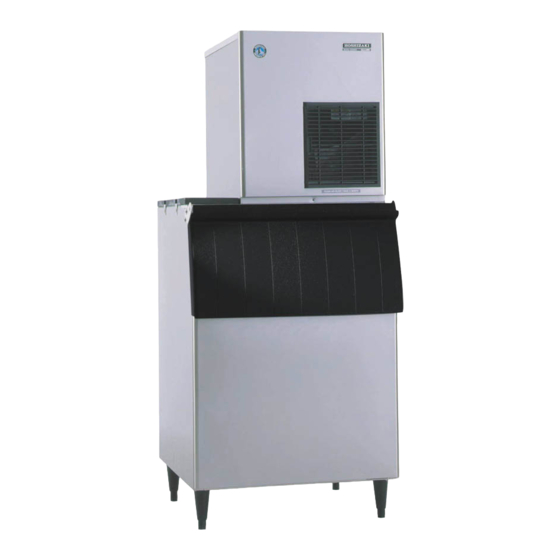
Modular flaker
Hide thumbs
Also See for F-801MAJ:
- Service manual (94 pages) ,
- Instruction manual (52 pages) ,
- Manual (2 pages)
Table of Contents


Need help?
Do you have a question about the F-801MAJ and is the answer not in the manual?
Questions and answers