Table of Contents
Advertisement
Quick Links
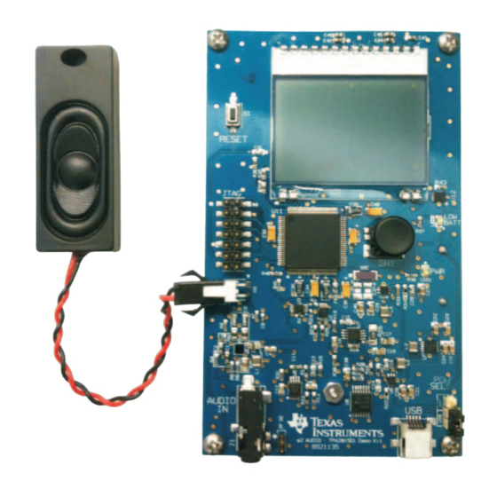
This user's guide describes the operation of the eZAudio TPA2015D1 Demonstration Kit. This document
provides setup instructions and design information including schematic, bill of materials, and printed-circuit
board (PCB) layout drawings.
.....................................................................................................................
1
1.1
1.2
2
2.1
2.2
3
3.1
4
4.1
4.2
4.3
1
2
3
4
5
6
.................................................................................................................
7
8
9
SLOU312 - June 2011
Submit Documentation Feedback
eZAudio TPA2015D1 Demonstration Kit
.........................................................................................................
.................................................................................
...........................................................................................................
...............................................................................................
.......................................................................................
......................................................................................................
.............................................................................................
...................................................................................
..........................................................................................................
.............................................................................................
....................................................................................................
.........................................................................................
....................................................................................
.......................................................................................................
........................................................................................
..............................................................................................................
.............................................................................................................
............................................................................................................
............................................................................................................
Copyright © 2011, Texas Instruments Incorporated
Contents
...................................................................
eZAudio TPA2015D1 Demonstration Kit
User's Guide
SLOU312 - June 2011
2
2
3
3
3
4
7
7
9
9
12
17
19
9
10
11
11
12
13
14
15
16
1
Advertisement
Table of Contents

Related Manuals for Texas Instruments eZAudio TPA2015D1


Summary of Contents for Texas Instruments eZAudio TPA2015D1
-
Page 1: Table Of Contents
User's Guide SLOU312 – June 2011 eZAudio TPA2015D1 Demonstration Kit This user’s guide describes the operation of the eZAudio TPA2015D1 Demonstration Kit. This document provides setup instructions and design information including schematic, bill of materials, and printed-circuit board (PCB) layout drawings. -
Page 2: Overview
The ezAudio TPA2015D1 can be powered by the included batteries or by a USB connection. Although the demonstration board is not designed for evaluation, the kit does contain a mini PCB that can be used for evaluation purposes. -
Page 3: Evaluation Board Specifications
Battery Indicator. A low-battery indicator is on the right side of the joystick. The LED turns on when the battery voltage drops below 3.7 V SLOU312 – June 2011 eZAudio TPA2015D1 Demonstration Kit Submit Documentation Feedback Copyright © 2011, Texas Instruments Incorporated... -
Page 4: Running The Demonstration
To get more steady current and power measurements, use the included sine wave MP3 file. 1. Joystick. Raise VDD to maximum by moving the joystick UP. SLOU312 – June 2011 eZAudio TPA2015D1 Demonstration Kit Submit Documentation Feedback Copyright © 2011, Texas Instruments Incorporated... - Page 5 5. Joystick. Move the joystick down twice to decrease the battery voltage. The current and power continue to decrease. SLOU312 – June 2011 eZAudio TPA2015D1 Demonstration Kit Submit Documentation Feedback Copyright © 2011, Texas Instruments Incorporated...
- Page 6 9. Joystick. Move the joystick to the right until VDD is displayed again. 10. Joystick. Move the joystick UP until VDD is at maximum. SLOU312 – June 2011 eZAudio TPA2015D1 Demonstration Kit Submit Documentation Feedback Copyright © 2011, Texas Instruments Incorporated...
-
Page 7: Hardware Description
When boost is enabled, the increased headroom for the output swing significantly reduces clipping. Hardware Description TPA2015D1 Features 2-W constant output, mono Class-D audio amplifier with integrated boost converter and battery tracking SpeakerGuard™ AGC SLOU312 – June 2011 eZAudio TPA2015D1 Demonstration Kit Submit Documentation Feedback Copyright © 2011, Texas Instruments Incorporated... - Page 8 ● Notebook PCs Audio Inputs OUT+ GAIN ● Portable clocking stations Gain Control TPA2015D1 OUT- AGC Control ● Portable DVD players DC/DC Enable Class-D Enable SLOU312 – June 2011 eZAudio TPA2015D1 Demonstration Kit Submit Documentation Feedback Copyright © 2011, Texas Instruments Incorporated...
-
Page 9: Schematics, Pcb And Bill Of Materials
90.9Kohms 0.001uF 90.9Kohms Voltage divider 392Kohms to accomodate 0.001uF VFS of A/D converter 39Kohms 27Kohms 18Kohms Figure 1. eZAudio TPA2015D1 Demonstration Kit Schematic SLOU312 – June 2011 eZAudio TPA2015D1 Demonstration Kit Submit Documentation Feedback Copyright © 2011, Texas Instruments Incorporated... -
Page 10: Evm Supply Generation Schematic
Data- UX60-MB-5ST 470mohms IBAT Meter Shunt resistor 0.1uF 0.1uF 100 Kohm Digital Pot 0.1uF 0.1uF 0.1uF 0.1uF Figure 2. EVM Supply Generation Schematic SLOU312 – June 2011 eZAudio TPA2015D1 Demonstration Kit Submit Documentation Feedback Copyright © 2011, Texas Instruments Incorporated... -
Page 11: Msp430 Schematic
Schematics, PCB and Bill of Materials www.ti.com MSP 430 Figure 3. MSP430 Schematic DISPLAY JOY STICK 5.1Kohms Figure 4. Display and Joystick Schematics SLOU312 – June 2011 eZAudio TPA2015D1 Demonstration Kit Submit Documentation Feedback Copyright © 2011, Texas Instruments Incorporated... -
Page 12: Printed-Circuit Board
Schematics, PCB and Bill of Materials www.ti.com Printed-Circuit Board Figure 5. Top Assembly SLOU312 – June 2011 eZAudio TPA2015D1 Demonstration Kit Submit Documentation Feedback Copyright © 2011, Texas Instruments Incorporated... -
Page 13: Bottom Copper
Schematics, PCB and Bill of Materials www.ti.com Figure 6. Bottom Copper SLOU312 – June 2011 eZAudio TPA2015D1 Demonstration Kit Submit Documentation Feedback Copyright © 2011, Texas Instruments Incorporated... -
Page 14: Top Copper
Schematics, PCB and Bill of Materials www.ti.com Figure 7. Top Copper SLOU312 – June 2011 eZAudio TPA2015D1 Demonstration Kit Submit Documentation Feedback Copyright © 2011, Texas Instruments Incorporated... -
Page 15: Copper Layer 2
Schematics, PCB and Bill of Materials www.ti.com Figure 8. Copper Layer 2 SLOU312 – June 2011 eZAudio TPA2015D1 Demonstration Kit Submit Documentation Feedback Copyright © 2011, Texas Instruments Incorporated... -
Page 16: Copper Layer 3
Schematics, PCB and Bill of Materials www.ti.com Figure 9. Copper Layer 3 SLOU312 – June 2011 eZAudio TPA2015D1 Demonstration Kit Submit Documentation Feedback Copyright © 2011, Texas Instruments Incorporated... -
Page 17: Bill Of Materials
Schematics, PCB and Bill of Materials www.ti.com Bill of Materials Table 1. Bill of Materials for eZAudio TPA2015D1 Demonstration Kit Mfr Part No. Ref Des Description Mfr Name CAPACITORS GRM21BR71A106KE51L C3,C17,C20,C22, CAP SMD0805 CERM 10UFD 10V10% X7R ROHS MURATA C24,C27,C46... - Page 18 Schematics, PCB and Bill of Materials www.ti.com Table 1. Bill of Materials for eZAudio TPA2015D1 Demonstration Kit (continued) Mfr Part No. Ref Des Description Mfr Name 293D475X5016A2T C33,C39 CAP,TAN,SMT, 4.7uF,16V,±5%,–55~85C VISHAY SPRAGE MPZ1608S601A FERRITE,SMT,0603,600 OHM,1A CC4V-T1 *HAND SOLDER*CRYSTAL,SMT,32.768kHz, 9pF±100ppm MICRO CRYSTAL...
-
Page 19: Appendix A Technical Specifications
L = 0 V and H = 3.3 V AGC0 and AGC1 change the inflection point for the TPA2015D1. They control the 3:1 analog switch to set the external AGC resistor. SLOU312 – June 2011 Technical Specifications Submit Documentation Feedback Copyright © 2011, Texas Instruments Incorporated... - Page 20 This control signal enables U6, the adjustable VDD regulator. This signal needs to be asserted HIGH after the analog switches and digital potentiometers have been set to default conditions. SLOU312 – June 2011 Technical Specifications Submit Documentation Feedback Copyright © 2011, Texas Instruments Incorporated...
- Page 21 Supply current (IDD_AD) – Is measured as a voltage out of INA333. Idd = Vmeas/4 • Output power – Is calculated as P = (Voutrms) / Rload SLOU312 – June 2011 Technical Specifications Submit Documentation Feedback Copyright © 2011, Texas Instruments Incorporated...
- Page 22 11. END = High 12. ENB = High Note: After the preceding sequence, the user can change gain and inflection point settings and activate/deactivate boost converter. SLOU312 – June 2011 Technical Specifications Submit Documentation Feedback Copyright © 2011, Texas Instruments Incorporated...
- Page 23 Evaluation Board/Kit Important Notice Texas Instruments (TI) provides the enclosed product(s) under the following conditions: This evaluation board/kit is intended for use for ENGINEERING DEVELOPMENT, DEMONSTRATION, OR EVALUATION PURPOSES ONLY and is not considered by TI to be a finished end-product fit for general consumer use. Persons handling the product(s) must have electronics training and observe good engineering practice standards.
- Page 24 IMPORTANT NOTICE Texas Instruments Incorporated and its subsidiaries (TI) reserve the right to make corrections, modifications, enhancements, improvements, and other changes to its products and services at any time and to discontinue any product or service without notice. Customers should obtain the latest relevant information before placing orders and should verify that such information is current and complete.
Need help?
Do you have a question about the eZAudio TPA2015D1 and is the answer not in the manual?
Questions and answers