Table of Contents
Advertisement
Quick Links
VQ No: VQA135
Instruction manual / Montageanleitung
SPECIFICATIONS
Wingspan:.........................2020mm (79.5in)
Length:..............................1540mm (60.6 in)
Electric Motor:.....................See next pager
Gas Engine:....................4T 40cc / 2T 30cc
RTF Weight: 7.1Kg / 15.7lbs (Will vary with
Equipment Used).
Radio:...............8-9 Channel / 8-9 Servos
Function: Ailerons-Elevator-Rudder-Throttle
Flaps-Optional Retractable Landing Gear.
WARNING! This radio controlled model is NOT a toy. If modified or flown carelessly it could go out of controll and
cause serious human injury or property damage. Before flying your airplane, ensure the air field is spacious enough.
Always fly it outdoors in safe areas and seek professional advice if you are unexperienced.
ACHTUNG! Dieses ferngesteuerte Modell ist KEIN Spielzeug! Es ist für fortgeschrittene Modellflugpiloten bestimmt,
die ausreichende Erfahrung im Umgang mit derartigen Modellen besitzen. Bei unsachgemässer Verwendung kann
hoher Personen- und/oder Sachschaden entstehen. Fragen Sie in einem Modellbauverein in Ihrer Nähe um
professionelle Unterstätzung, wenn Sie Hilfe im Bau und Betrieb benötigen. Der Zusammenbau dieses Modells ist
durch die vielen Abbildungen selbsterklärend und ist für fortgeschrittene, erfahrene Modellbauer bestimmt.
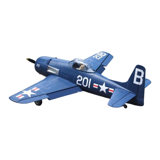
Radio control model / Flugmodel
U.S NAVY
BEARCAT
ALL BALSA, PLYWOOD CONSTRUCTION AND ALMOST READY TO FLY
TECHNISCHE DATEN
Spannweite:...................................2020mm
Lange:............................................1540mm
Elektroantrieb.............(siehe nächste Seite)
Verbrennerantrieb:..........................26-30cc
Fluggewicht:.......................................7.1Kg
Fernsteuerung......8-9 Kanal / 8-9 Servos
Advertisement
Table of Contents

Related Manuals for VQ Radio Control Model Bearcat F8F


Summary of Contents for VQ Radio Control Model Bearcat F8F
- Page 1 Radio control model / Flugmodel U.S NAVY BEARCAT VQ No: VQA135 ALL BALSA, PLYWOOD CONSTRUCTION AND ALMOST READY TO FLY Instruction manual / Montageanleitung TECHNISCHE DATEN SPECIFICATIONS Wingspan:......2020mm (79.5in) Spannweite:........2020mm Length:......1540mm (60.6 in) Lange:..........1540mm Electric Motor:.....See next pager Elektroantrieb.....(siehe nächste Seite) Gas Engine:....4T 40cc / 2T 30cc Verbrennerantrieb:......26-30cc RTF Weight: 7.1Kg / 15.7lbs (Will vary with...
- Page 2 REQUIRED FOR OPERATION (Purchase separately) Extension cord for aileron servos: 80cm(x2) Extension cord for flap servos: 50cm(x2) Extension cord for retract servos: 50cm(x2) Extension cord for Rx battery pack: 30cm(x1) Extension cord for gear door servo: 30cm(x1) 8 standard servos and 1 mini servo (for gas engine).
-
Page 3: Section 1- Wing: Flap-Aileron
SECTION 1- WING: FLAP-AILERON Servo mount RARE BEAR Servo hatch Servo mount Servo hatch 1-Move the aileron and flap servo hatch out of the wing 2-Install the aileron servo to the aileron servo hatch as shown. 3-Install the flap servo to the flap servo hatch as shown. Note: If you use only one channel for both the left and right Flap, in this case, remember to install the left and right flap servo in a same direction. -
Page 4: Section 2 - Fixed Gear
SECTION 2 - FIXED GEAR 3x20mm Nylon gear Main strap landing gear Ply gear mount flat Square Gear plastic mount 3x20mm Step 2C Step 2A Step 2B 3x15mm screw Step 2D ...1 ...1 Step 2E 3x12mm screw ..2 5mm collar ...1 Step 2F Do the same way with other wing half. -
Page 5: Section 3 - Struts
SECTION 3 - STRUTS Step 3A Step 3B Step 3C Step 3D Note: Do not glue the gear door to the strut at this time... -
Page 6: Section 4 - Retract Landing Gear
SECTION 4 - RETRACT LANDING GEAR Wing (front-view) Step 4A Dowel Glue the dowel to the rib root, marking sure that the dowel perpendicular to surface of the rib root. 8mm dowel Step 4B SECTION 5 - ENGINE Step 5A Fuselage - front view A1 A2 Step 5B... -
Page 7: Section 6 - Fuel Tank
SECTION 5 - ENGINE continued Step 5D E1=E2=E3=E4 (The long of the aluminum tubes are the same and depend of your engine) Note: The aluminum tubes for the engine installation not include. Step 5E SECTION 6 - FUEL TANK Step 6B Note: secure the 5mm nuts in place using silicon sealer. -
Page 8: Section 7 - Electric Motor
Motor mounting plate SECTION 7 - ELECTRIC MOTOR Step 7A Step 7B Fuselage - front view -Using a aluminum motor mounting plate as a template, mark the plywood motor mounting plate where the four holes are to be drilled. (The long of the aluminum tubes are same and depend of your motor) -Remove the aluminum motor mounting plate and drill a 7/32”(5mm) hole through the plywood at each of the four Note: The aluminum tubes for the motor installation not include. -
Page 9: Section 8 - Gear Door
SECTION 8 - GEAR DOOR Step 8A Step 8B 25x10mm aluminum tube Bend the gear door push rod for smooth work. 10x25mm aluminum tube ..3 (for each side) Gear door push rod ..1 (for each side) Do the same way with other side... -
Page 10: Section 9 - Joining The Wing
SECTION 9 - JOINING THE WING Step 9A 12x390mm aluminum tube 25x870mm aluminum tube Step 9B... - Page 11 SECTION 9 - JOINING THE WING continued Step 9C...
-
Page 12: Section 10 - Horizontal Stabilizer
SECTION 9 - JOINING THE WING continued 5x20mm screw ...1 (for each side) Step 9D 5x20mm screw Note: Turn the plastic bolts on the left and right SECTION 10 - HORIZONTAL STABILIZER side of the fuselage, full the canopy hatch out of the fuselage first. - Page 13 SECTION 10 - HORIZONTAL STABILIZER continued Pencil When you are satisfied with the alignment , use a pencil to carefully trace around the top and bottom of the stabilizer where it meets the fuselage. Note, it is important not to disturb the alignment of the stabilizer.
-
Page 14: Section 14 - Elevator
SECTION 14 - ELEVATOR RARE BEAR 5 minutes Step 14B HORIZONTAL STABILIZER Petroleum jelly When satisfied with the and alignment, hinge the elevator to the horizontal Step 14A stabilizer using 5 minute epoxy. Make sure to apply a thin layer of epoxy to the top and bottom of both hinges and to inside the hinge slots. -
Page 15: Section 12 - Rudder Torque Rod Bearing
SECTION 12 - RUDDER TORQUE ROD BEARING Petroleum jelly Step 12A 1- Cut 22mm (7-8”) long slot along the hinge line in the trailing edge of the vertical stabilizer for the rudder torque rod bearing. 2- Apply a thin layer of petroleum jelly to only the pivot of the torque rod bearing. Step 12B Glue the rudder torque rod bearing into the slot you cut previously in the vertical stabilizer Using the thin CA glue. -
Page 16: Section 13 - Rudder
SECTION 13 - RUDDER Without using glue yet, push the rudder and its hinges into the hinge slots in the trailing edge of the vertical Step 13A stabilizer. There should be a minimal hinge gap and the end of the rudder should not rub against the vertical stabilizer. -
Page 17: Section 15 - Tail Wheel
SECTION 14 - ELEVATOR CONTROL HORN Elevator push rod Elevator push rod Elevator control horn Elevator control horn Bottom-view Plastic control horn ....2 2x20mm screw ....4 SECTION 15 - TAIL WHEEL Step 15A Step 15B 1- Slide the wire, straight end first, into the push rod tube 2x8mm 2- Insert the Z-bend into the hole on the tail wheel control arm. -
Page 18: Section 16 - Servo
SECTION 16 - SERVO Throttle servo (in case of gas engine using) and position of the throttle servo depend of engine Gear door servo Rudder and tail wheel servo Switch hole Right elevator servo Left elevator servo Connector ..7 3mm set Screw Push rod D=.050”(1.2mm) 2 mm... -
Page 19: Section 17 - Guns
SECTION 17 - GUNS Step 17A Step 17B Step 18B SECTION 18 - COWLING Step 18A Cut the opening Cut the opening Secure the plastic dummy engine in place using 5 min.Epoxy 2.5x10mm screw 2.5x10mm screw Step 18C ..6... - Page 20 SECTION 19 - STRUTS Sand here Strut Wooden ring Gear door Lightly sand the wooden rings to be sure that the struts locks in down position. Sand here With the retract in the retracted position, carefully move the gear door on the strut until the gear door nearest with the gear door on the fuselage, mark on the struts.
-
Page 21: Section 20 - Balance And Control Surface
SECTION 20 - BALANCE AND CONTROL SURFACE Note: Adjust the location of the battery pack to achieve this C.G location. (152 ~ 162mm) DO NOT try to fly an out-of balance model! Wing center section (20mm) (15mm) (20mm) (15mm) AILERON STROKE ELEVATOR STROKE (25mm) (25mm)
Need help?
Do you have a question about the Bearcat F8F and is the answer not in the manual?
Questions and answers