Advertisement
Instruction manual / Montageanleitung
WARNING! This radio controlled model is NOT a toy. If modified or flown carelessly it could go out of controll and
cause serious human injury or property damage. Before flying your airplane, ensure the air field is spacious enough.
Always fly it outdoors in safe areas and seek professional advice if you are unexperienced.
ACHTUNG! Dieses ferngesteuerte Modell ist KEIN Spielzeug! Es ist für fortgeschrittene Modellflugpiloten bestimmt,
die ausreichende Erfahrung im Umgang mit derartigen Modellen besitzen. Bei unsachgemässer Verwendung kann
hoher Personen- und/oder Sachschaden entstehen. Fragen Sie in einem Modellbauverein in Ihrer Nähe um
professionelle Unterstätzung, wenn Sie Hilfe im Bau und Betrieb benötigen. Der Zusammenbau dieses Modells ist
durch die vielen Abbildungen selbsterklärend und ist für fortgeschrittene, erfahrene Modellbauer bestimmt.
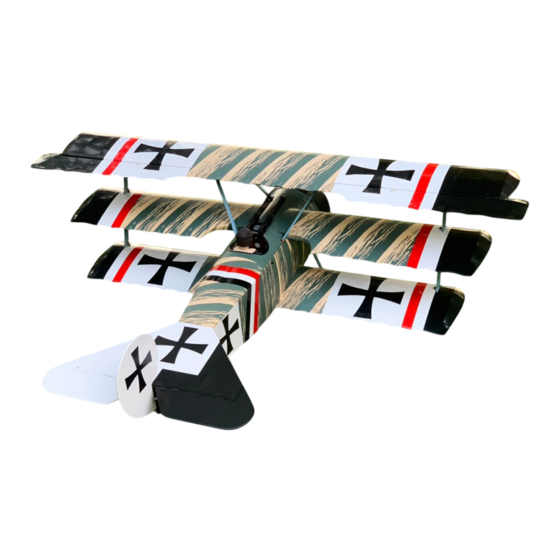
Radio control model / Flugmodel
1850mm Wingspan
ALL BALSA, PLYWOOD CONSTRUCTION AND ALMOST READY TO FLY
SPECIFICATIONS
Wingspan:......................................1850mm
Length .......................... ................1420mm
Diameter of cowl: 230mm, Length: 120mm
Electric Motor:................Boost 100 (460KV)
Glow Engine:....................................4T: 140
Gas Engine:...................2T: 25cc / 4T: 30cc
RTF Weight: 7.5 - 7.8kg (will vary with
equipment use).
Radio:....................6 Channels / 6 Servos
Function: Aileron-Elevator-Rudder-Throttle.
Advertisement
Table of Contents

Related Manuals for VQ Radio Control Model FOKKER DR1


Summary of Contents for VQ Radio Control Model FOKKER DR1
- Page 1 Radio control model / Flugmodel 1850mm Wingspan ALL BALSA, PLYWOOD CONSTRUCTION AND ALMOST READY TO FLY Instruction manual / Montageanleitung SPECIFICATIONS Wingspan:........1850mm Length ..........1420mm Diameter of cowl: 230mm, Length: 120mm Electric Motor:....Boost 100 (460KV) Glow Engine:........4T: 140 Gas Engine:....2T: 25cc / 4T: 30cc RTF Weight: 7.5 - 7.8kg (will vary with equipment use).
- Page 2 REQUIRED FOR OPERATION (Purchase separately) Radio minimum 6 channels Aileron: 50cmx2 pcs Aileron: 20cmx2 pcs Rx battery pack: 30cmx1 pcs 2T gas engine: 25cc 4T gas engine: 30cc Recommended engine: 2T: Zenoah 26cc 4T: Saito FG-33R3 Silicone tube 6 Standard sevos Electric motor recommended: BOOST 100 (460KV) Elevator : 2 standard servo...
- Page 3 FOKKER Dr 1 HISTORY The Fokker Dr.1 (Dreidecker, “triplane” in Germany), often known simply as the Fokker Triplane, was a World War l fighter aircraft built by Fokker-Flugzeuwerke. The Dr.l saw widespread service in the spring of 1918. It became famous as the aircraft in which Manfred von Richthofen agained his last 17 victories (plus two earlier ones in the Fokker F.l prototype in September 1917), and in which he was killed on 21 April 1918.
-
Page 4: Engine Mount
1- Engine mount This drawing shows the engine mount Secure the aluminum mount in with the engine facing down. place using x10mm hex bolt. Aluminum mount Aluminum mount Note: In case of using Saito FG-30 gas engine, The engine mount will be included in the box For other engine brands we are not sure if engine mount included with the engine or not... - Page 5 2- Engine mount Insert the blind-nut onto each of the four holes make above. Reposition the engine mount on to the fire-wall and secure them with four 4x25mm hexagonal bolts. 4x25mm hexagonal bolt - washer ....4 Blind-nut ....4 Position the engine to the engine mounts so the distance from the prop hub to the fire-wall from 145-150mm.
- Page 6 3- Electric motor mount Using a aluminum motor mounting plate as a template, mark the plywood motor mounting plate where the four holes are to be drilled. ! Align the mark on wooden motor mounting plate with the mark on the Remove the aluminum motor mounting fire-wall.
-
Page 7: Electric Motor
4- Electric motor Attach the four 6x100mm bolts and nuts to the fire-wall as shown. 6x100mm bolt ..4 6mm nut....12 6mm washer..16 Secure the Motor to the wooden motor mounting plate using the four 4mm bolts. 4x15mm bolt / nut...4 145-150mm Adjust the wooden motor mount so the distance from the prop hub to the fire-wall... -
Page 8: Main Landing Gear
5- Main landing gear Main landing gear Main landing gear... - Page 9 6- Main landing gear continued 3mm hex bolt 3mm hex bolt ..4 3x10mm screw ..4 3x10mm screw...
- Page 10 7- Main landing gear continued Rubber band Nylon strap ..6 3x12mm screw ..12 3.7mm collar 4mm collar 3.7mm collar ..4 4mm collar ..6...
-
Page 11: Horizontal Stabilizer
8- Main landing gear continued 9- Horizontal stabilizer... - Page 12 10- Horizontal stabilizer continued B’ B=B’ Check the alignment of the horizontal stabilizer. When you are satisfied with the alignment, use a pencil to trace around the Cut away only bottom of the stabilizer where it meets the fuselage. the covering bottom side.
- Page 13 11- Horizontal stabilizer brace 3mm connector ..2 Note: This hole is pre-drilled and has a blindnut inside. 2x20mm bolt - nut - washer Turn to adjust the length of tail brace ...2 12- Elevator ! Securely glue together. If coming off during fly, Thin CA you lose control of your air plane.
- Page 14 13- Rudder ! Securely glue together. If coming off during fly, you lose control of your air plane. 14- Tail wheel control horn 3x12mm 1.5mm 3x12mm 2.8mm collar Control horn ....2 2x20mm bolt ...4 2mm nut ....2 Control horn / flat ..2 set...
- Page 15 15- Tail wheel horn Tail wheel horn...1 2x15mm.....1 16- Servo Throttle servo (GP) FUSELAGE - TOP VIEW Right elevator servo Rudder servo Left elevator servo 2mm connector .....2 Threadlocker...
- Page 16 17- Linkages Right elevator push rod Rudder steering cable Rudder steering cable Left elevator push rod 2x8mm metal tube cable ..4 ..2 ..2 2x8mm metal tube ..4...
- Page 17 18- Linkages continued 19- Low wing: dowel 6x20mm wooden dowel Thin CA Note: The wooden dowels must be perpendicular with the root rib. Note: You should grind the tip of the wooden dowels to make it easier to push into the root rib.
- Page 18 20- Middle wing: dowel 6x20mm wooden dowel Thin CA 21- High wing: dowel 6x20mm wooden dowel Thin CA...
-
Page 19: Aileron Servo
22- Aileron servo 3mm connector .....2 Threadlocker 2.5mm Control horn and 2x30mm bolt 2 Set 23- Aileron linkage Aileron push-rod ..2 High wing - Bottom view... - Page 20 24- Center wing: Aileron servo extension cord Center wing - Bottom view 25- Wing jig assembly FOKKER Dr1 RIGHT...
- Page 21 26- Wing jig assembly continued Thin CA Thin CA 27- Wing jig inatallation...
- Page 22 28- Wing jig installation continued 6x45mm nylon bolt Insert 12mm dia. aluminum tube 6x45mm nylon bolt through the fuselage as show. Included in hardware bag 29- Wing braces Insert the aluminum wing mount to one end of the wing brace and secure it in place using the 3x10mm hex bolt as show.
- Page 23 30- Center wing installation Thread the center wing through the wing jig and adjust the center wing so that it is centered on the fuselage axis (A=A’ as show). hold it in place with the rubber bands (not included). Rubber band A’...
- Page 24 31- Remove the wing jig Remove the 6x45mm nylon bolt. Remove the aluminum tube. Remove the rubber bands, two 6x45mm nylon bolts and the aluminum tube, pull the wing jig out of the wing. 32- Aluminum wing joiner 12x410mm Aluminum tube ...2 19x318mm Aluminum tube ...2...
- Page 25 33- Lower wing installation 6x45mm nylon bolt Included in hardware bag 6x45mm nylon bolt 34- Middle wing installation 6x45mm nylon bolt 6x45mm nylon bolt Included in hardware bag...
- Page 26 34- Outer wing installation Included in hardware bag 35- Wing brace assembly Note: The arrow is the direction facing up Towards the wing tip Towards the fuselage ..8 3x10mm hex bolt ..8 3mm washer / nut ..8...
- Page 27 36- Wing brace installation 2x8mm screw 3x10mm hex bolt Close all the hatches on the top of all ..8 wings using 2x8mm screw. 3mm washer / nut ..8 2x8mm screw ..24 3x12mm hexbolt 3x12mm hexbolt 3x12mm hexbolt 3x12mm hexbolt Secure the wing struts in place using the 3x12mm hex bolts.
-
Page 28: Cockpit Installation
38- Machine-gun installation 38- Machine-gun installation Thin CA 39- Pilot figure installation 15 min. Epoxy 40- Cockpit installation Four positions (two left and two right) for mounting plastic bolts. - Page 29 41- Cockpit installation continued 4x20mm nylon bolt 4x20mm nylon bolt ..4 42- Cowl 3x10mm screw ..7...
- Page 30 43- Lead mount Note: You can buy the lead mount at Home deport. Lead mount These parts must be purchased separately 44- Lead mount continued...
- Page 31 45- Put lead on the lead mount Lead to balance the center of gravity of the model. Note: The weight of the lead varies depending on the type of the engine you use (from 700 to 1700gr). 46- Balance THE CENTER OF GRAVITY IS LOCATED 108-115mm BACK FROM THE LEADING EDGE OF THE UPPER WING.
- Page 32 47- Balance continued 2- Turn the plane upside down and place it on the CG stand where it was marked with masking tape. Note: Add the piece of plywood on the surface of the wing so the weight of the plane does not damage of the wing. 3- If the nose of the plane rise, the plane is tail heavy.
Need help?
Do you have a question about the FOKKER DR1 and is the answer not in the manual?
Questions and answers