
Related Manuals for Daikin LREQ-BY1


Summary of Contents for Daikin LREQ-BY1
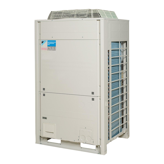
- Page 1 INSTALLATION MANUAL Air cooled refrigeration condensing unit LREQ5B7Y1 LREQ6B7Y1 LREQ8B7Y1 LREQ10B7Y1 LREQ12B7Y1 LREQ15B7Y1 LREQ20B7Y1...
- Page 2 2PW40200-15T...
- Page 3 2PW40200-15T...
-
Page 4: Table Of Contents
• Be sure to install an earth leakage breaker. • This document is an installation manual for the Daikin Air Cooled Failure to install an earth leakage breaker may result in electric Refrigeration Condensing Unit. Before installing the unit, read this shocks or fire. -
Page 5: Special Notice Of Product
• Do not touch the refrigerant piping, water piping or internal parts CAUTION during and immediately after operation. It could be too hot or too cold. Give it time to return to normal temperature. If you must touch This unit is already filled with a certain amount of R410A. it, wear protective gloves. -
Page 6: Before Installation
BEFORE INSTALLATION LREQ5, LREQ6 LREQ8, LREQ10, LREQ12 CAUTION • When installing the indoor unit, refer to the installation manual provided for the indoor unit. 1, 2, 3 1, 2, 3 • Optional accessories are required for the installation of the product. -
Page 7: Selection Of Location
• If the work conditions in the following figure do not apply, contact An inverter condensing unit may cause electronic noise generated your dealer or Daikin directly. from AM broadcasting. Examine where to install the main <... -
Page 8: Handling The Unit
HANDLING THE UNIT Corner-hole Independent Beam Beam foundation foundation foundation foundation Decide on the transportation route. (horizontal) (vertical) If a forklift is to be used, pass the forklift arms through the large openings on the bottom of the unit. Not required Not required for LREQ5 for LREQ5... -
Page 9: Refrigerant Piping
REFRIGERANT PIPING To Piping Work Contractors • Never open the shutoff valve until the steps specified in "7. FIELD WIRING" on page 11 "8-3 Checking of device and installation conditions" on page 16 of piping. • Do not use flux at the time of brazing and connecting refrigerant pipes. -
Page 10: Selection Of Piping Material
6-1 Selection of piping material • Make sure that the inner side and outer side of the piping used is clean and free of contaminants, such as sulphur, oxide, dust, chips, oil and fat, and water. It is desirable that the maximum oil adhesion in the piping is 30 mg per 10 m. •... -
Page 11: Protection Against Contamination When Installing Pipes
6-2 Protection against contamination when 6-5 Connecting the refrigerant piping installing pipes CAUTION Protect the piping to prevent moisture, dirt, dust, etc. from entering the piping. • In addition to gas and liquid shutoff valves, this unit has a maintenance shutoff valve (see diagram below). Place Installation period Protection method... - Page 12 Removing Pinch Piping CAUTION Precautions when connecting field piping. WARNING • Perform brazing at the gas stop valve before brazing at the liquid Never remove the pinched piping by brazing. stop valve. Failure to observe the instructions in procedure below properly may •...
- Page 13 Tightening torque Handling Precautions for Service Port Check with the following table the sizes of shutoff valves incorporated • Work on the service port with a charge hose provided with a by each model and the tightening torque values of the respective pushing rod.
-
Page 14: Field Wiring
When connected at lateral side (bottom) Indoor unit side Remove the knock hole on the bottom frame and route the piping under the bottom frame. Branch piping LREQ5~12 Make the piping T-joint slant downward Gas side shutoff valve Liquid side shutoff valve Main piping Brazing Gas side... -
Page 15: Example Of Wiring Entire System
• If not factory installed, a main switch or other means for 6 Caution input disconnection, having a contact separation in all poles providing 7 Warning input full disconnection under overvoltage category III condition, shall be 8 Alarm panel installed in the fixed wiring. 9 Control board (field supply) 10 Timer •... -
Page 16: Procedure For Power Supply Wiring
• If small animals might enter the unit, block off any gaps (hatching Phase and Minimum Recommended Voltage parts) with material (field supply). frequency circuit amp. fuses Knockout hole LREQ5 3~ 50Hz 380-415V 12.8A (For low-voltage wiring) LREQ6 3~ 50Hz 380-415V 13.7A LREQ8... -
Page 17: Procedure For Wiring Inside Units
Remote switch wiring connections • Do not finish strand wire with solder. • When installing a remote switch, clamp as indicated by the Cup washer following diagram: Crimp-style terminal Secure remote switch wiring to the resin block using a Cut out section clamp (field supply). -
Page 18: Inspection And Pipe Insulation
Conduit • Airtight Perform wiring carefully so that the wiring will not come in contact Pressurize the high-pressure section of the system (liquid piping) to 3.8 MPa (38 bar) and the low-pressure section of the system with the port and part. -
Page 19: Checking Of Device And Installation Conditions
CHECKS AFTER WORK COMPLETION • Liquid pipe arrival minimum temperature 0°C Gas pipe arrival minimum temperature –45°C • Make sure the following works are complete in accordance with the • Reinforce the insulation material for the refrigerant piping installation manual. according to the environment of thermal installation. - Page 20 [The evaporation temperature setting] d.Turn off the operation switch of the outdoor unit after the speci- Refer to the following table for the evaporation temperature. fied amount of refrigerant is replenished. (To prevent liquid • The evaporation temperature is set up by dip switches (DS1). compression) e.[Caution] Fully open the shutoff valves on the gas and liquid sides...
-
Page 21: Test Run
[Check through sight glass] How to check malfunction code By operating the pushbutton switches on the PCB, malfunction code items can be displayed on the condensing unit. 1. Make sure that the LED “H1P” is off. Sight glass Full of liquid A little foam Foam always (If the LED is on, press the MODE button (BS1) once.) -
Page 22: Additional Refrigerant Amount
12. ADDITIONAL REFRIGERANT AMOUNT Refrigeration 12-1 Calculation method showcase This product must fill the refrigerant in the field. Outdoor unit Calculate the amount of refrigerant replenishment according Blower coil to the following points and note the amount of the refrigerant Frozen in the list shown below. - Page 24 *4PW74302-1 D 0000000L* 4PW74302-1D 2016.11...
Need help?
Do you have a question about the LREQ-BY1 and is the answer not in the manual?
Questions and answers