
Related Manuals for Amprobe AT-4005-A


Summary of Contents for Amprobe AT-4005-A
- Page 1 AT-4000-A Series Advanced Wire Tracer Users Manual GlobalTestSupply www. .com Find Quality Products Online at: sales@GlobalTestSupply.com...
- Page 2 GlobalTestSupply www. .com Find Quality Products Online at: sales@GlobalTestSupply.com...
- Page 3 AT-4000-A Series Advanced Wire Tracer Users Manual P/N 2756641 Rev 002 11/2013, 6001563 A © 2013 Amprobe Test Tools. All rights reserved. GlobalTestSupply www. .com Find Quality Products Online at: sales@GlobalTestSupply.com...
- Page 4 Limited Warranty and Limitation of Liability Your Amprobe product will be free from defects in material and workmanship for one year from the date of purchase unless local laws require otherwise. This warranty does not cover fuses, disposable batteries or damage from accident, neglect, misuse, alteration, contamination, or abnormal conditions of operation or handling.
-
Page 5: Table Of Contents
AT-4000-A Series Advanced Wire Tracer CoNTENTS Precautions ....................4 Introduction ....................4 AT-4000-A Product Description..............5 Unit Description ..................5 Application Notes ..................9 Using the R-4000 with Thumbwheel............9 Using the T-4000-A Transmitter ............. 10 Using the A2202 Clamp-On Transmitter Accessory ......11 Finding Opens .................... -
Page 6: Precautions
Advanced Wire Tracer has a history of providing safe, reliable operation in tracing energized wires, locating circuit breakers and locating wires shorted to the ground. The Amprobe wire tracer has the capability of tracing non-energized wires, locating open breakers and locating open wires. -
Page 7: At-4000-A Product Description
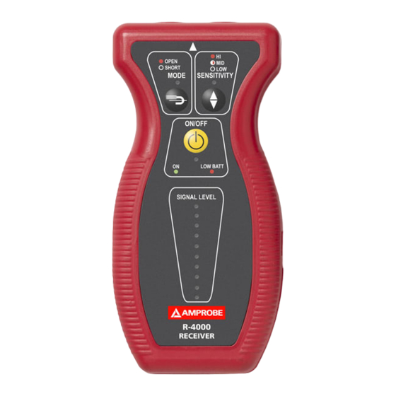
AT-4000-A PRodUCT dESCRIPTIoN The AT-4000-A consists of two units: T-4000-A Transmitter (32.768KHZ, 9-300 V ac or dc) R-4000 Receiver (Non-position sensitive, Open / Short Tracing) Unit description R-4000 Receiver It has two built-in detectors that are tuned to pick up the 32.768Khz signals generated by the T-4000-A transmitter. - Page 8 ➊ ➍ ➋ ➎ ➌ ➏ ➐ R-4000 Receiver ➎ Sensitivity control ➊ LED Indicator: ON - OPEN ➏ Power ON/OFF OFF - SHORT ➐ LED Indicator: ➋ Mode control Green - Unit ON Red - Low battery ➌ Sensitivity control thumbwheel ➍...
- Page 9 ➊ ➍ ➋ ➌ ➎ ➏ T-4000-A Transmitter ➊ Banana plug jack ➋ Signal level switch ➌ Power ON/OFF ➍ Fuse (inside) holder ➎ 24 Volt jack ➏ 9V Battery compartment GlobalTestSupply www. .com Find Quality Products Online at: sales@GlobalTestSupply.com...
- Page 10 When connecting to a circuit as a load, the signal will be present anywhere between the T-4000-A and the power source. Line side or upstream, no signal will be present on wiring on the other side of the transmitter (load side or downstream). For example, a transmitter connected to a circuit breaker will produce no signal on that circuit.
-
Page 11: Application Notes
without the need for direct connection. (Note: When using the battery booster (B2024 or B2025) the unit will work in ultra high “U-HI” mode only. Remove the battery booster to return to normal operation.) B2024 Battery Pack 24 V Nickel-cadmium rechargeable battery pack is custom designed to be light weight, small, and durable. -
Page 12: Using The T-4000-A Transmitter
a) OPEN Tracing: LED ON b) SHORT Tracing: LED OFF 3. Press SENSITIVITY push button to select the sensitivity level. a) LOW Sensitivity: LED OFF b) MEDIUM Sensitivity: LED Blinking c) HIGH Sensitivity: LED ON Solid 4. Locate the thumbwheel on the left side of the unit a) Select MEDIUM Sensitivity Level b) Rotate thumbwheel counterclockwise to decrease sensitivity level... -
Page 13: Using The A2202 Clamp-On Transmitter Accessory
6. Select the signal transmission level (LOW, MID, HIGH) by pressing on the signal level push button. It takes about 2 seconds for the transmission to start after you last hit the push button. (Note: When using the battery booster (B2024 or B2025) the unit will work in ultra high “U-HI”... -
Page 14: Finding Opens
be boosted significantly by using the B2024 battery Pack. (Note: When using the battery booster (B2024 or B2025) the unit will work in ultra high “U-HI” mode only. Remove the battery booster to return to normal operation.) One typical application for the A2202 is to access the hot wire at the panel in order to identify the ‘downstream’... -
Page 15: Finding Ground Faults
8. Select the ‘HIGH’ sensitivity by pressing the SENSITIVITY push button (the LED must be ‘ON’). 9. Starting from the T-4000-A, trace the conductor. The open will be at the point you begin to lose signal. At that point, select the ‘MID’ sensitivity mode (the LED must be ‘blinking’) in order to pinpoint the exact location of the Open. -
Page 16: Tracing Wires In Conduit
2. Attach one clip to the faulted wire and the other one to ground. 3. Press the signal level push button and select the appropriate level. 4. If possible, ground all adjacent conductors. 5. The R-4000 receiver can then be used to trace the wire. The signal should remain relatively constant until you pass the ground fault. -
Page 17: Tracing Energized Wires
7. If two or more breakers produce the same signal strength indication. Move the receiver away slowly from each of them and watch the indication level. (Refer to Figure 17) Tracing Energized Wires 1. Connect the Alligator Clip Cord set to the T-4000-A. 2. -
Page 18: Locating Individual Wires In A Bundle (Energized And Non-Energized Lines)
Locating Individual Wires in a Bundle (Energized and Non-energized Lines) 1. Attach alligator clip set to the T-4000-A. 2. Verify that the voltage on the line does not exceed the T-4000-A rating. 3. Connect one alligator clip to the wire you wish to identify and the other to a separate ground using the 25’... -
Page 19: Maintenance
2. Use of the B2024 battery or the B2025 converter is recommended. 3. Set the T-4000-A to ‘HIGH’ mode. 4. Set the R-4000 to ‘SHORT’ mode and ‘LOW’ sensitivity. 5. Trace the conduit. (Refer to Figure 20) Note: When using the battery booster (B2024 or B2025) the unit will work in ultra-high “U-HI”... -
Page 20: Replacement Parts
C2901 Alligator Clip Banana Plug Cord Set C2902 Grounding Test Lead 25-FT MTL-G Carrying Case AT-4000-A CC-AT-4000 Users Manual www.Amprobe.com Fuse 1000V 0.25A FA 6X46MM FA6X46MM TRoUBLEShooTING Symptom Possible Cause Solution LCD Segments of the 9V battery is low in... -
Page 21: Specifications
SPECIFICATIoNS General Operating Temperature: 0 to 120° F (-18°C to 49°C) Storage temperature: -40° to 150° F (-40° to 66°C) Case material: ABS Case size: 0.55” x 0.26” (14 x 6.7 mm) R-4000 Receiver Detectors: electromagnetic coil array pick up for short mode. Electrostatic plate pick up for open mode. - Page 22 Weight: 0.32 LB (143.5g) Current output of the Signal: Low mode: 11 mA average, 30 mA peak Medium mode: 12 mA average, 36 mA peak High mode: 13 mA average, 63 mA peak Fuse: Fast acting 250 mA @ 1000V (6X46mm) P/N: FA6X46MM Signal output (9V supply): High setting: 0.74 V ac Medium setting: 0.61 V ac...
- Page 23 Figure 1. Figure 2. GlobalTestSupply www. .com Find Quality Products Online at: sales@GlobalTestSupply.com...
- Page 24 Figure 3. Figure 4. Figure 5. GlobalTestSupply www. .com Find Quality Products Online at: sales@GlobalTestSupply.com...
- Page 25 Figure 6. Figure 7. Figure 8. GlobalTestSupply www. .com Find Quality Products Online at: sales@GlobalTestSupply.com...
- Page 26 In either SHORT or OPEN MODE, the unit is non position sensitive Figure 9. Figure 10. GlobalTestSupply www. .com Find Quality Products Online at: sales@GlobalTestSupply.com...
- Page 27 Figure 11. Figure 12. Figure 13. GlobalTestSupply www. .com Find Quality Products Online at: sales@GlobalTestSupply.com...
- Page 28 Figure 14. Figure 15. Figure 16. GlobalTestSupply www. .com Find Quality Products Online at: sales@GlobalTestSupply.com...
- Page 29 Figure 17. Figure 18. GlobalTestSupply www. .com Find Quality Products Online at: sales@GlobalTestSupply.com...
- Page 30 Figure 19. Figure 20. Figure 21. GlobalTestSupply www. .com Find Quality Products Online at: sales@GlobalTestSupply.com...
- Page 31 GlobalTestSupply www. .com Find Quality Products Online at: sales@GlobalTestSupply.com...
- Page 32 Visit www.Amprobe.com for • Catalog • Application notes • Product specifications • User manuals Amprobe ® www.Amprobe.com info@amprobe.com Everett, WA 98203 Tel: 877-AMPROBE (267-7623) Amprobe Europe ® Beha-Amprobe In den Engematten 14 79286 Glottertal, Germany Please Tel.: +49 (0) 7684 8009 - 0...
Need help?
Do you have a question about the AT-4005-A and is the answer not in the manual?
Questions and answers