
Related Manuals for Amprobe AT-7000


Summary of Contents for Amprobe AT-7000
- Page 1 AT-7000 Advanced Wire Tracers AT-7020 AT-7030 User Manual Manuel de l’utilisateur Manual de usuario GlobalTestSupply www. .com Find Quality Products Online at: sales@GlobalTestSupply.com...
-
Page 2: User Manual
AT-7000 Advanced Wire Tracer AT-7020 AT-7030 User Manual 10/2017, 4394127 Rev B ©2017 Amprobe Test Tools. All rights reserved. GlobalTestSupply www. .com Find Quality Products Online at: sales@GlobalTestSupply.com... -
Page 3: Table Of Contents
AT-7000 Series CONTENTS 1. PRECAUTIONS AND SAFETY MEASURES ............. 2. KIT COMPONENTS ....................2.1 AT-7000-R Receiver ......................6 2.2 AT-7000-T Transmitter ....................8 2.3 TL-7000 Test Lead & Accessory Kit ................9 2.4 SC-7000 Signal Clamp (AT-7030 Kit) ................10 3. MAIN APPLICATIONS .................... -
Page 4: Precautions And Safety Measures
Safety information The product complies with: • UL/IEC/EN 61010-1, CAN/CSA C22.2 No. 61010-1, Pollution Degree 2, Measurement category IV 600 V (AT-7000-R); Category IV 300V MAX (AT-7000-T) • IEC/EN 61010-2-033 • IEC/EN 61010-2-032 • IEC/EN 61010-031 (test leads) •... - Page 5 • Only use the test lead provided with the Meter or UL Listed Probe Assembly rated CAT IV 600V or better. • Do not use HOT STICK to operate the AT-7000-R Receiver around voltage more than 600V GlobalTestSupply www.
- Page 6 1. PRECAUTIONS AND SAFETY MEASURES Symbols used in this product Battery status – Displays the remaining battery charge Home – Return to home screen when selected Help – Enters to the help mode when selected Settings – Enters to the settings menu when selected Volume–...
-
Page 7: Kit Components
This tester meets water and dust protection IP40 per IEC60529 Ed 2.1 (2001). Do not use in rainfall! The tester is double insulated for protection per EN61010-1:2010 3rd Ed to CAT IV 600V. (AT-7000-R) and CAT IV 300V MAX (AT-7000-T) CAUTION: Do not connect the Transmitter to a separate ground in Electrically Susceptible Patient areas of a health care facility. -
Page 8: At-7000-R Receiver
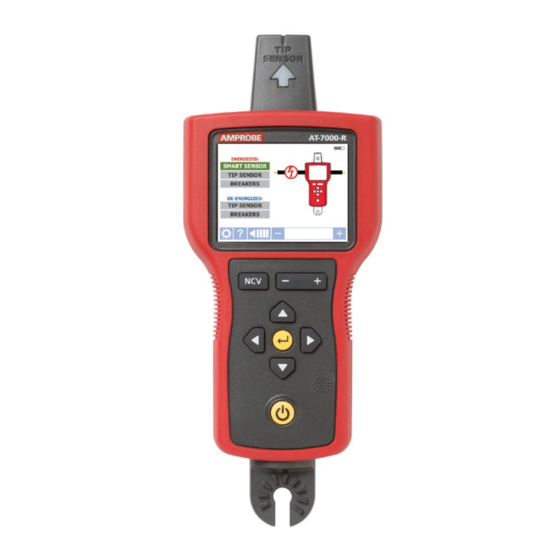
2. KIT COMPONENTS 2.1 AT-7000-R Receiver The AT-7000-R Receiver detects the signal generated by the AT-7000-T transmitter along wires using either the TIP SENSOR or SMART SENSOR and displays this information on the full color TFT LCD display. Active tracing using a signal generated by the AT-7000-T Transmitter The SMART SENSOR works with a 6 kHz signal generated along energized wires (above 30V AC/DC) and provides an indication of the wire position and direction relative to the receiver. - Page 9 2. KIT COMPONENTS ENERGIZED: Main applications DE-ENERGIZED: Help guide Setting menu Buzzer volume adjustment Sensitivity adjustment Figure 1a: Overview of all elements on home screen Home menu Figure 1b: Overview of all elements on the setting menu Language English, French, German, Spanish, Italian Backlight 25%, 50%, 75%, 100% Setting...
-
Page 10: At-7000-T Transmitter
If the circuit is energized the red LED in the upper left corner of the AT-7000-T transmitter will light. IMPORTANT! Note that the red LED light will turn on when connected to an energized circuit. -
Page 11: Tl-7000 Test Lead & Accessory Kit
Figure 2a: Overview of AT-7000-T Transmitter LCD Screen 2.3 TL-7000 Test Lead & Accessory Kit All AT-7000 kits come with our complete test leads & accessory kit. The kit supports a wide range of standard and specialty applications and contains test leads and adaptors as... -
Page 12: Sc-7000 Signal Clamp (At-7030 Kit)
The clamp accessory is used for applications when there is no access to the bare conductors. The clamp attachment enables the AT-7000-T Transmitter to induce a signal through the insulation into either energized or de-energized wires. The signal will travel through the wire in both HAND GUARD directions and into all the branches. -
Page 13: Main Applications
(with opposite direction) through the second one. This causes creation of two electromagnetic fields around each wire with opposite direction. These opposing fields will partially or completely cancel each other out, making wire tracing difficult if not impossible. AT-7000-R Not recommended. This wire connection causes... -
Page 14: Tracing Energized Wires
*Note: Please note that if working with GFCI protected circuits, this method will trip the GFCI protection. Refer to Special Applications, section 4.1 “GFCI-Protected Circuit Wire Tracing” for alternative tracing methods. Set up the AT-7000-T Transmitter: 1. Press ON/OFF key to turn on the transmitter. - Page 15 3. MAIN APPLICATIONS - SMART SENSOR (Energized) Using AT-7000-R Receiver 1. Press ‘ON/OFF’ push button to turn on the receiver and wait for the home screen (boot up time is around 30 seconds). 2. Select SMART SENSOR mode by using the directional arrows to highlight this operating mode and pressing the yellow ENTER button.
-
Page 16: Tip Sensor Energized
GFCI protection. Refer to Special Applications, section 4.1 “GFCI-Protected Circuit Wire Tracing” for alternative tracing methods. Set up the AT-7000-T Transmitter: 1. Press ON/OFF key to turn on the transmitter. 2. Verify that the test leads are properly connected - the red LED voltage status should indicator should be on, indicating that the circuit is energized. - Page 17 3. MAIN APPLICATIONS - TIP SENSOR (Energized) Using AT-7000-R Receiver 1. Press ‘ON/OFF’ push button to turn on the receiver and wait for the home screen (boot up time is around 30 seconds). 2. Select Energized TIP SENSOR mode by using the directional arrows to highlight this operating mode and pressing the yellow “ENTER”...
-
Page 18: Tracing De-Energized Wires
(metal building structure, metal water pipe, or ground wire on a separate circuit). Set up the AT-7000-T Transmitter: 1. Press ON/OFF key to turn on the transmitter. 2. The red LED voltage status should indicator should be off, indicating that the circuit is de-energized. - Page 19 3. MAIN APPLICATIONS - TIP SENSOR (De-Energized) Using AT-7000-R Receiver 1. Press ‘ON/OFF’ push button to turn on the receiver and wait for the home screen (boot up time is around 30 seconds). 2. Select De-Energized TIP SENSOR mode by using the directional arrows to highlight this operating mode and pressing the yellow “ENTER”...
-
Page 20: Identifying Breakers And Fuses
The simplified direct connection to hot and neutral wire will NOT trip the GFCI circuit. Set up the AT-7000-T Transmitter: 1. Press ON/OFF key to turn on the transmitter. 2. Verify that the test leads are properly connected - the red LED voltage status indicator should be on, indicating that the circuit is energized. - Page 21 3. MAIN APPLICATIONS - BREAKERS (Energized) Step 1 - SCAN: 1. The unit will automatically start in SCAN mode as shown in Figure 3.3b. 2. Scan each breaker for a half second by touching it with the Tip Sensor. Make sure the groove on the Tip Sensor is parallel to the breaker lengthwise (See Figure 3.3d) 3.
-
Page 22: Breaker De-Energized (De-Energized Circuits)
Figure 3.3f identification. Set up the AT-7000-T Transmitter: 1. Press ON/OFF key to turn on the transmitter. 2. The red LED voltage status should indicator should be off, indicating that the circuit is de-energized. -
Page 23: Non-Contact Voltage Mode (Ncv)
3. MAIN APPLICATIONS - BREAKERS (De-Energized) 4. Step 2 - LOCATE a) Select LOCATE mode by using the directional arrows to highlight this operating mode and pressing the yellow “ENTER” button. b) Scan each breaker again for a half second each by touching it with the Tip Sensor. Active red arrow indicates scanning process. -
Page 24: Special Applications
2. Use steps described in the De-Energized TIP SENSOR mode to connect the transmitter and perform tracing. (see section 3.2) The tracing signal generated by the AT-7000-T transmitter will be conducted along the wire as long as there is continuity in the metal conductor. To find the place of fault, trace the wire until the signal stops. -
Page 25: Finding Shorts
Connect the circuit as shown in the illustration below. AT-7000-T Setup the receiver to Energized TIP SENSOR mode. Start tracing the cable until you find the location where the signal stops. To verify the place of the fault, move the transmitter to the other end of the wire and repeat tracing from the opposite end. -
Page 26: Tracing Wires In Metal Conduit
4. SPECIAL APPLICATIONS 4.4 Tracing Wires in Metal Conduit The AT-7000-R receiver will not be able to pick up the signal from the wire through the metal conduit. The metal conduit will completely shield the tracing signal. Note: The receiver will be able to detect wires in non-metallic conduit. For these applications follow general tracing guidelines. -
Page 27: Tracing Underground Wires
4. SPECIAL APPLICATIONS 4.7 Tracing Underground Wires The AT-7000 can trace wires underground, the same way it can locate wires behind walls or floors. Perform tracing as described in Energized SMART SENSOR mode or Energized / De-Energized TIP SENSOR modes. -
Page 28: No Access To Bare Conductors (Signal Clamp)
When clamp is connected to the transmitter, it enables the AT-7000-T to induce signal to energized or de-energized wire through the insulation. The signal will travel through the wire both directions and it will affect all the branches. This method is safe to use for any sensitive electronic equipment. -
Page 29: Locating Loads (Signal Clamp)
Access to Bare Conductors (Inductive Clamp)’. 3. Scan face plates of receptacles and wires connecting loads with the TIP Sensor of the AT-7000-R. If using on a de-energized system you must set the receiver to de-energized TIP SENSOR mode. 4. All the wires, receptacles and loads that have a strong signal as indicated by the AT-70000-R are connected to the breaker. -
Page 30: Maintenance - Battery And Fuse Replacement
5. MAINTENANCE Changing battery for transmitter: The battery compartment on the back of the AT-7000-T is designed to make it easy for the user to change the battery. A screw is added to secure the battery in case the unit is dropped. - Page 31 5. MAINTENANCE Changing receiver battery: The battery compartment on the back of the AT-7000-R is designed to make changing batteries easy. Four (4) AA 1.5V alkaline or 1.2V rechargeable batteries may be used. Battery Cover Screws 4 x AA batteries Figure 5.2: Changing receiver battery...
- Page 32 5. MAINTENANCE Transmitter fuse replacement: Figure 5.4: Transmitter fuse replacement Warning: To avoid shock, injury, or damage to the Transmitter, disconnect test � leads before opening case. 1. Disconnect all test leads from the Transmitter. 2. Make sure that the transmitter is turned off. 3.
-
Page 33: Specifications
6. SPECIFICATIONS AT-7000-R AT-7000-T SC-7000 LCD size 3.5" 1.77" LCD Dimensions 2.76 x 2.07 1.1 x 1.38 in LCD Resolution 320 x 240 128 x 160 (pixels) LCD type RGB x TFT Color LCD Backlight mDDR 64 MB 64 MB... - Page 34 6. SPECIFICATIONS IP Rating IP52 IP40 IP52 Sampling rate 6.25kHz Signal: 62.5 kSPS 62.5KSPS 32.768kHz: 256KSPS NCV: 62.5 kSPS Signal Response Audible beep, Numeric display bargraph display, numeric display Response time Smart mode: 750 mSec Voltage measurement: instantaneous 1.5 Sec Tip Sensor Energized: 300 mSec Battery monitoring:...
- Page 35 6. SPECIFICATIONS Voltage output 180 Vp-p 1.5 Vp-p (Clamp mode) De-Energized Range Detection Smart mode (Open air) Pinpointing: Around 1.97-in (5 cm) radius (±2%) Direction indication: Up to 5FT (152.4cm) (±2%) TIP Sensor: Energized Pinpointing: Around 1.97-in (5 cm) (±1%) Detection: Up to 22-FT (670.56cm) (±1%) TIP Sensor: De-Energized...
Need help?
Do you have a question about the AT-7000 and is the answer not in the manual?
Questions and answers