Table of Contents

Subscribe to Our Youtube Channel
Related Manuals for Amprobe AT-8000 Series


Summary of Contents for Amprobe AT-8000 Series
- Page 1 99 Washington Street Melrose, MA 02176 Phone 781-665-1400 Toll Free 1-800-517-8431 Visit us at www.TestEquipmentDepot.com AT-8000 Advanced Wire Tracers AT-8020 AT-8030 User Manual ENG FRE SENSOR CAT IV 600V AC AT-8000-R AT-8000-T...
- Page 2 AT-8000 Advanced Wire Tracer AT-8020 AT-8030 User Manual 3/2020, 6012207 A ©2020 Amprobe. All rights reserved.
- Page 3 Limited Warranty and Limitation of Liability Your Amprobe product will be free from defects in material and workmanship for one year from the date of purchase unless local laws require otherwise. This warranty does not cover fuses, disposable batteries or damage from accident, neglect, misuse, alteration, contamination, or abnormal conditions of operation or handling.
-
Page 4: Table Of Contents
AT-8000 Advanced Wire Tracer CONTENTS 1. PRECAUTIONS AND SAFETY MEASURES ............. 2. KIT COMPONENTS ....................2.1 AT-8000-R Receiver ......................6 2.2 AT-8000-T Transmitter ....................8 2.3 CT-400 Signal Clamp ......................11 3. MAIN APPLICATIONS .................... 3.1 Tracing Energized Wires ....................13 • Using the Receiver in Energized SMART SENSOR mode ........14 •... -
Page 5: Precautions And Safety Measures
• If the Transmitter or Receiver will not be used for a long time, remove the batteries to prevent leakage in the instruments. • Use Amprobe approved cables and accessories only. Safety precautions In many instances, dangerous levels of voltage and/or current may be present. Therefore, it is important to avoid direct contact with any uninsulated voltage/current carrying surfaces. - Page 6 1. PRECAUTIONS AND SAFETY MEASURES � Warnings: Read Before Using To avoid the possibility of electric shock or personal injury: • Use the Product only as specified in this manual or the protection provided by the instrument may be compromised. •...
- Page 7 1. PRECAUTIONS AND SAFETY MEASURES Symbols used in this product Battery status – Displays the remaining battery charge. Home – Return to home screen when selected. Help – Enters to the help guide when selected. Settings – Enters to the settings menu when selected. Indicates the volume is muted.
-
Page 8: Kit Components
1. PRECAUTIONS AND SAFETY MEASURES This manual contains information and warnings that must be followed for safe operation and maintenance of the instrument. If the Product is used in a manner not specified by the manufacturer, the protection provided by the Product may be impaired. This Product meets water and dust protection IP52 (Receiver) and IP40 (Transmitter and signal clamp) per IEC 60529. -
Page 9: At-8000-R Receiver
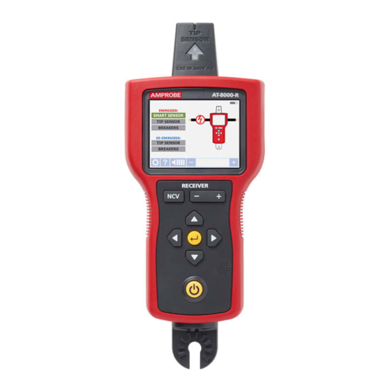
2. KIT COMPONENTS 2.1 AT-8000-R Receiver The AT-8000-R Receiver detects the signal generated by the AT-8000-T Transmitter along wires using either the Tip Sensor or Smart Sensor and displays this information on the full color TFT LCD display. Active tracing using a signal generated by the AT-8000-T Transmitter The Smart Sensor works with a 6 kHz signal generated along Energized wires (above 30 V AC/DC) and provides an indication of the wire position and direction relative to the Receiver. - Page 10 2. KIT COMPONENTS Battery status ENERGIZED: Main applications DE-ENERGIZED: Help guide Setting menu Buzzer volume adjustment Sensitivity adjustment Figure 2.1b: Overview of home screen elements x.x.x Home menu Figure 2.1c: Overview of settings menu elements Language English, French, Spanish, Portuguese Backlight 25%, 50%, 75%, 100% Setting...
-
Page 11: At-8000-T Transmitter
2. KIT COMPONENTS 2.2 AT-8000-T Transmitter The AT-8000-T Transmitter works on Energized and De-energized circuits up to 600 V AC/DC in Category I through Category IV electrical environments. VOLTAGE WARNING INDICATOR 1. Red: Energized 2. Off: De-energized 3. Blinking: Overvoltage AT-8000-T TRANSMITTER TRANSMISSION MODE... - Page 12 2. KIT COMPONENTS Transmitter signal modes: High Signal (Hi) – The HIGH mode function is recommended for most wire tracing applications on Energized and De-energized circuits including breaker/fuse location. This function will be used the majority of the time. Low Signal (Lo) – The LOW mode function is only appropriate for the most demanding and precise wire tracing applications, as it limits the signal level generated by the Transmitter in order to pinpoint the wire location more precisely.
- Page 13 2. KIT COMPONENTS Working with the Transmitter When the Transmitter is on and connected to the circuit with test leads, it checks for voltage. A red Voltage Warning Indicator will light up if the Transmitter detects dangerous voltage levels above 30 V AC/DC. IMPORTANT! The Voltage Warning Indicator light will blink when overvoltage (>...
-
Page 14: Ct-400 Signal Clamp
2. KIT COMPONENTS 2.3 CT-400 Signal Clamp (included with AT-8030, optional for AT-8020) The Signal Clamp accessory is used for applications when where is no access to the bare conductors. The clamp attachment enables the Transmitter to induce a signal through the insulation into either wires. -
Page 15: Main Applications
3. MAIN APPLICATIONS IMPORTANT NOTICE, PLEASE READ BEFORE STARTING TRACING � Avoiding signal cancellation problems with a separate ground connection The signal generated by the Transmitter creates an electromagnetic field around the wire. This field is what is detectable by the Receiver. The clearer this signal, the easier it is to trace the wire. -
Page 16: Tracing Energized Wires
3. MAIN APPLICATIONS - ENERGIZED WIRES 3.1 Tracing Energized Wires Connecting Transmitter test leads 1. Connect the green and red test leads to the Transmitter (polarity does not matter). 2. Using provided test leads accessories, connect AT-8000-T the green wire to a separate ground (metal building structure, metal water pipe, or ground wire on a separate circuit). -
Page 17: Tm Mode
AT-8000-T TRANSMITTER 3. MAIN APPLICATIONS - SMART SENSOR (Energized) Note: The LOW signal precision mode can be used to limit the signal level generated by the Transmitter in order to more precisely pinpoint wire location. A lower signal level reduces BLINKING coupling to neighboring wires and metal objects and helps to avoid misreading due to ghost... -
Page 18: Using Receiver In Energized Tip Sensor Mode
3. MAIN APPLICATIONS - TIP SENSOR (Energized) Figure 3.1f: Receiver locked on wire Using AT-8000-R Receiver in Energized TIP SENSOR mode TIP SENSOR mode is used for the following applications: pinpointing a wire in a bundle, tracing in corners and confined spaces such as junction boxes or inside enclosures. 1. -
Page 19: Tracing De-Energized Wires
3. MAIN APPLICATIONS - TIP SENSOR (Energized) Align Tip groove Figure 3.1i: Figure 3.1h: Rotating the Receiver to Aligning the Tip Sensor with the wire align with the wire 3.2 Tracing De-energized Wires Connecting Transmitter test leads 1. Connect the green and red test leads to the Transmitter (polarity does not matter). -
Page 20: Using Receiver In De-Energized Tip Sensor Mode
3. MAIN APPLICATIONS - TIP SENSOR (De-Energized) Using AT-8000-R Receiver in De-energized TIP SENSOR mode TIP SENSOR De-energized TIP SENSOR mode is used for general wire tracing, pinpointing wires in bundles, tracing in tight corners and confined spaces such as junction boxes or inside enclosures. 1. - Page 21 3. MAIN APPLICATIONS - TIP SENSOR (De-Energized) AT-8000-T AT-8000-T Figure 3.3a: Simplified direct connection Figure 3.3b: Separate ground connection (Preferred) Transmitter connection - Energized and De-energized systems Connection of the Transmitter is the same for Energized and De-energized breaker/fuse locating. Connecting the test leads 1.
- Page 22 3. MAIN APPLICATIONS - BREAKERS (Energized and De-Energized) Energized and De-energized breaker/fuse locating & BREAKERS Receiver Process Overview Tracing breakers/fuses is a two-step process: SCAN - Scan each breaker/fuse for one second. The Receiver will record tracing signal levels. LOCATE - The Receiver will indicate the single breaker/fuse with the strongest recorded signal. Using AT-8000-R Receiver 1.
-
Page 23: Non-Contact Voltage Mode (Ncv)
3. MAIN APPLICATIONS - BREAKERS (Energized) Step 2 - LOCATE 1. Select LOCATE mode by using the directional arrows and pressing the yellow ENTER button (Figure 3.3d). 2. Rescan each breaker/fuse by touching each with the Tip Sensor for a second. Active red arrow indicates scanning process. -
Page 24: Special Applications
4. SPECIAL APPLICATIONS Figure 3.4: Voltage detection in NCV mode using Tip Sensor 4.1 GFCI-Protected Circuit Wire Tracing Connecting AT-8000-T Transmitter to GFCI protected circuits. Connecting the Transmitter to an Energized GFCI protected circuit using separate ground method will trip the GFCI protection. Use following methods to work with GFCI protected circuits (for De-energized GFCI-protected outlet that is not tripped, you can connect test leads directly to the outlet contacts using De-energized TIP SENSOR mode) Method 1 –... -
Page 25: Finding Breaks/Opens
4. SPECIAL APPLICATIONS 4.2 Finding Breaks/Opens It is possible to pinpoint the exact location where a wire is broken, even if the wire is located behind walls, floors or ceilings. 1. Make sure that wire is De-energized. 2. Use the steps described in section 3.2 to connect the Transmitter and perform tracing with the Receiver set to De-energized TIP SENSOR mode. -
Page 26: Tracing Wires In Metal Conduit: Junction Box Method
4. SPECIAL APPLICATIONS Figure 4.3: Finding a short 4.4 Tracing Wires in Metal Conduit: Junction Box Method The AT-8000-R Receiver will not be able to pick up the signal from the wire through the metal conduit. The metal conduit will completely shield the tracing signal. Note: The Receiver will be able to detect wires in non-metallic conduit. -
Page 27: Tracing Shielded Wires
4. SPECIAL APPLICATIONS 4.6 Tracing Shielded Wires Shielded wires prevent the Receiver from detecting a tracing signal when following the standard user instructions. To effectively trace shielded wire, follow these procedures. If shielded wire is grounded at the far-end: 1. Setup Transmitter in Loop mode by pressing HIGH button for two seconds. Verify that the Loop LED is ON. -
Page 28: Tracing Underground Wires
4. SPECIAL APPLICATIONS 4.7 Tracing Underground Wires The AT-8000 can trace wires underground, the same way it can locate wires behind walls or floors. Perform tracing as described in Energized SMART SENSOR mode or Energized / De-Energized TIP SENSOR modes. You can use a hot sick attachment to make tracing more ergonomic and convenient. -
Page 29: Sorting Bundled Wires
4. SPECIAL APPLICATIONS 4.9 Sorting Bundled Wires Identifying a specific wire in a bundle: 1. Connect the Transmitter using Energized or De-Energized TIP SENSOR mode. If connecting to energized wire, make sure the Transmitter is connected on the load side. 2. -
Page 30: Mapping A Circuit Using Test Leads Connection
4. SPECIAL APPLICATIONS 4.10 Mapping a Circuit using Test Leads Connection Mapping a circuit can be only performed on a De-energized circuit when using test leads connection. 1. Switch the breaker/fuse to the OFF position. 2. Set up the Transmitter and Receiver as described in the De-energized Wire Tracing as described in section 3.2. -
Page 31: Signal Clamp - Closed Loop Circuits
4. SPECIAL APPLICATIONS 4.12 Signal Clamp - Closed Loop Circuits Closed loop, De-energized and low impedance circuits The clamp accessory is used for applications where there is no access to a bare conductor to connect the test leads. When the clamp is connected to the Transmitter, it enables the Transmitter to induce a signal to the Energized or De-energized wire through the insulation. - Page 32 4. SPECIAL APPLICATIONS Using AT-8000-R Receiver 1. Press power button to turn on the Receiver; home screen may take up to 30 seconds to load. 2. Select Energized TIP SENSOR mode by using the directional arrows and pressing the yellow ENTER button. 3.
-
Page 33: Signal Clamp - Mapping Circuits
4. SPECIAL APPLICATIONS 4.13 Signal Clamp - Mapping Circuits The clamp accessory can be used to map loads to specific breakers/fuses on both Energized and De-energized systems. There is no need to disconnect power. 1. Clamp the CT-400 around the wire at the breaker/fuse panel. 2. -
Page 34: Maintenance
5. MAINTENANCE 5.1 Battery Replacement Changing the Transmitter Batteries The battery compartment on the back of the Transmitter is designed to make it easy for the user to change the batteries. A screw is added to secure the battery in case the unit is dropped. - Page 35 5. MAINTENANCE Manual Selecting of Transmitter Battery Type The type of batteries being used-Alkaline or rechargeable NiMH-are recognized automatically during power up of the device or may be defined manually by the user. Set battery type as alkaline: 1. Make sure that the Transmitter is turned off. 2.
- Page 36 5. MAINTENANCE Changing the Receiver Batteries The battery compartment on the back of the Receiver is designed to make it easy for the user to change the batteries. A screw is added to secure the battery in case the unit is dropped.
-
Page 37: Fuse Replacement
5. MAINTENANCE 5.2 Fuse Replacement Transmitter Fuse Replacement � Warning: To avoid shock, injury, or damage to the Transmitter, disconnect test leads before opening case. 1. Disconnect all test leads from the Transmitter. 2. Make sure the Transmitter is turned off. 3. -
Page 38: Specifications
6. SPECIFICATIONS Features AT-8000-R AT-8000-T CT-400 Measurement CAT IV 600 V CAT IV 600 V CAT IV 600 V, Category CAT III 1000 V Operating 0 to 600 V AC/DC 0 to 600 V AC/DC 0 to 1000 V AC Voltage Operating Energized: 6.25 kHz... - Page 39 6. SPECIFICATIONS General specifications Features AT-8000-R AT-8000-T CT-400 Display Size 3.5 in (89 mm) LEDs Display Dimensions 2.76 x 2.07 in (70 x 52 mm) (W x H) Display Resolution 320 x 240 Display Type Color TFT LCD LEDs Display Color Operating mode LEDs: red Battery status LEDs: green, yellow, red...
- Page 40 6. SPECIFICATIONS Accessory specifications Features ADPTR-SCT TL-8000-INT Measurement Category CAT II CAT IV 600 V (test leads) CAT IV 600 V (alligator clips) CAT II 300 V (outlet adapters) Operating Voltage and Current 102 to 253 V AC, 4 A max. 600 V, 10 A max.
- Page 41 Test Equipment Depot - 800.517.8431 - 99 Washington Street Melrose, MA 02176 TestEquipmentDepot.com...
Need help?
Do you have a question about the AT-8000 Series and is the answer not in the manual?
Questions and answers