
Related Manuals for Meterman PM55A


Summary of Contents for Meterman PM55A
- Page 1 PM55 Automatic Precision Pocket Meter Users Manual • Mode d’emploi • Bedienungshandbuch • Manual d’Uso • Manual de uso PN 2153049 August 2004 2004 Meterman Test Tools. All rights reserved. Printed in Taiwan...
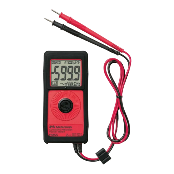
- Page 2 Press for 2 seconds to turn meter on. LCD display Rotary switch to select functions and to turn the power on or off SELECT-button to select alternate functions and turn the power off and on. Permanently attached red test lead for positive (+) polarity and black test lead for ground reference (-)
-
Page 3: Table Of Contents
PM55 Pocket Meter Contents Introduction ....................2 Safety Information...................2 Symbols Used in this Manual................3 Turning the Meter On and Off ................3 Making Measurements ..................4 AutoTect Mode...................5 Continuity, Audible With Symbolic Display ............5 Electric Field EF-Detection, VolTect ............6 Voltage......................8 Resistance ....................8 Frequency ....................8 Capacitance....................8 V dc, V ac, and Line-Level Hz................8... -
Page 4: Introduction
PM55 offers VolTect™, a built-in non-contact voltage detection of AC voltage. Although very small, this meter is fully UL safety rated to CAT III levels and is UL listed. The Meterman PM55 precision meter includes measurement extras such as capacitance, frequency, DC microamps and safety extras such as transient protection to 4 kV and overload protection to 600 V. -
Page 5: Symbols Used In This Manual
• Exercise extreme caution when: measuring voltage >20 V // current >10 mA // AC power line with inductive loads // AC power line during electrical storms // current, when the fuse blows in a circuit with open circuit voltage > 600 V // servicing CRT equipment. •... -
Page 6: Making Measurements
Making Measurements All measurements described in this manual use the Red test lead for positive (+) polarity and Black test lead for Ground reference (-) unless otherwise specified AutoTect mode is the default function in Auto V.Ω position. Press the SELECT button momentarily to select and step through the functions: •... -
Page 7: Autotect Mode
AutoTect Mode This AutoTect feature automatically selects measurement function of V dc, V ac, or resistance based on the input via the test leads. ● With no input, the meter displays Auto when it is ready. ● With no voltage signal but a resistance below 6 MΩ is present, the meter displays the resistance value. -
Page 8: Electric Field Ef-Detection, Voltect
Electric Field EF-Detection, VolTect With Auto displayed on the LCD, press the SELECT button momentarily 2 times to select the EF-Detection feature. The meter displays EF when it is ready. Signal strength is indicated as a series of bargraph segments on the display and variable beep tones. - Page 9 Note For Maximum sensitivity, hold the meter away from the VolTect corner.
-
Page 10: Voltage
Voltage With Auto on the LCD, press the SELECT button 3 times to select V ac function. The meter displays LoZBV when it is ready.This function is auto-ranging. With Auto on the LCD, press the SELECT button 4 times to select V dc. The meter displays LoZ V when it is ready. -
Page 11: Diode
Diode Turn the rotary selector to the GR /600 Ω position. Diode test is the default function. The reading shows the approximate voltage drop across the test leads. Normal forward voltage drop (forward biased) for a good silicon diode is between 0.400 V to 0.900 V. A reading higher than that indicates a leaky diode (defective). -
Page 12: Troubleshooting
Troubleshooting If the instrument fails to operate, check battery, leads, and replace battery as necessary. Double-check operating procedure as described earlier in this manual. If the display locks up, press the SELECT button for approximately 6 seconds to reset the microprocessor. If the instrument voltage-resistance input is subjected to high voltage transient (mostly caused by lightning or switching surge to your system) by accident or abnormal conditions of operation, the series fusible resistors... -
Page 13: Repair
Resellers are not authorized to extend any other warranty on Meterman’s behalf. To obtain service during the warranty period, return the product with proof of purchase to an authorized Meterman Test Tools Service Center or to a Meterman dealer or distributor. See Repair Section for details. THIS WARRANTY IS YOUR ONLY REMEDY. - Page 14 Additionally, in the United States and Canada In-Warranty repair and replacement units can also be sent to a Meterman Test Tools Service Center (see below for address). Non-Warranty Repairs and Replacement – US and Canada Non-warranty repairs in the United States and Canada should be sent to a Meterman Test Tools Service Center.
-
Page 15: Specifications
Specifications General Specifications Display and Update Rate: 3-5/6 digits 6000 counts; Updates 5 per second nominal Operating Temperature: 0 °C - 40 °C Relative Humidity: Maximum 80% R.H. up to 31 °C, decreasing linearly to 50% R.H. at 40 °C Altitude: Operating below 2000 m Storage Temperature: -20 °C ~ 60 °C, <... - Page 16 E.M.C. Meets EN61326 (1997, 1998/A1), EN61000- 4-2 (1995), and EN61000-4-3 (1996). This product complies with requirements of the following European Community Directives: 89/ 336/ EEC (Electromagnetic Compatibility) and 73/ 23/ EEC (Low Voltage) as amended by 93/ 68/ EEC (CE Marking). However, electrical noise or intense electromagnetic fields in the vicinity of the equipment may disturb the measurement circuit.
- Page 17 AC Voltage Range Accuracy 50 Hz – 60 Hz ±(1.5%+5 dgt) 6.000 V, 60.00 V, 450.0 V, 600 V CMRR: > 60 dB @ dc to 60 Hz, Rs=1 kΩ Input Impedance: AutoTect Lo-Z V ac: 160 kΩ, 160 pF nominal Hi-Z ACV: 5MΩ, 90pF nominal ...
- Page 18 Resistance Range Accuracy 600.0 Ω ±(2.0%+6 dgt) ±(1.2%+6 dgt) 6.000 kΩ ±(1.0%+4 dgt) 60.00 KΩ, 600.0 KΩ ±(2.0%+4 dgt) 6.000 MΩ Open Circuit Voltage: 0.4VDC typical 1)AutoTect is for 6.000kΩ ~ 6.000MΩ ranges; 2)Add 40 dgt to specified accuracy while reading is below 20% of range Frequency Range...
- Page 19 DC µA Current Range Accuracy Burden Voltage 400.0 µA ±(1.5%+3 dgt) 6 mV/µA 2000 µA ±(1.2%+3 dgt) 6 mV/µA AC µA Current Range Accuracy Burden Voltage 400.0 µA ±(2.0%+3 dgt) 6 mV/µA 2000 µA ±(1.5%+3 dgt) 6 mV/µA Voltect Typical Voltage Bar Graph Indication 20 V to 80 V 45 V to 125 V...
- Page 20 Audible Continuity Tester (600 Ω Range) Open Circuit Voltage: 0.4 V dc typical Audible Threshold: >175 Ω ± 125 Ω...
Need help?
Do you have a question about the PM55A and is the answer not in the manual?
Questions and answers