
Related Manuals for TBB Projecta PMDC-30


Summary of Contents for TBB Projecta PMDC-30
- Page 1 INTELLI DC-DC CHARGER (Intelli-Jay Integration) Need technical help? P/No. PMDC-30 (C4975F) Contact Projecta on 1800 294 294...
-
Page 2: General & Safety Information
GENERAL & SAFETY INFORMATION This section contains important safety and operation instructions. Please read and retain this manual for future reference. The PMDC-30 should be installed by a qualified Auto Electrician with knowledge of caravan electrical systems. The following recommendations are to be conducted prior to installation: •... -
Page 3: Block Diagram
2.2 BLOCK DIAGRAM Figure 2-1: Block Diagram of PMDC-30 Alternator Motor DC/DC Intelli-Jay Transformer battery Converter Temperature detect Voltage detect Voltage detect Switch The charging efficiency of the PMDC-30 is up to 96%. PMDC-30 also supports communication of RS485. PMDC-30 will treat it as conventional engine rather than Euro 6 engine. -
Page 4: Battery Temperature Compensation
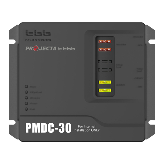
2.4 BATTERY TEMPERATURE COMPENSATION Battery temperature is a key factor in correct charging, the charging formula must be adjusted (automatically and in real time) according to the actual battery temperature to ensure that battery are fully charged but not overcharged or undercharged. - Page 5 STRUCTURE AND DIMENSION 3.1 EXTERIOR AND DIMENSION Figure 3-1: PMDC-30 front view Figure 3-2: PMDC-30 dimensions...
-
Page 6: Connectors And Terminals
3.2 CONNECTORS AND TERMINALS Figure 3-3: Connectors and terminals Table 3-1: Connectors and terminals guide Print PMDC-30 Remarks Circuit colours and labelling Connects to positive of Or connects to positive Red + Label Alternator Alternator of motor battery “Aux+” Connects to negative of Or connects to positive Black –... -
Page 7: Status Indicators
3.3 STATUS INDICATORS Table 3-3: LED codes Print Colour Status Description Working normal Power Green No working or Low Power Mode Motor battery voltage in the range Alternator Green Flashing Motor battery voltage high Motor battery voltage low Charging battery at bulk or absorption stage Charge Green Flashing... -
Page 8: Installation Space
4.4 INSTALLATION SPACE For adequate ventilation, it is important to leave space around where the PMDC-30 is installed. See recommended spacing dimensions below. Figure 4-1: The required dimensions for ventilation ≥ 50m m ≥ 50m m ≥ 100m m ≥ 50m m 4.5 MOUNTING HOLES Find an appropriate mounting surface, flat and rigid. -
Page 9: Dip Switch Setting
4.6 DIP SWITCH SETTING Dip Switches Set output current and battery type UP = OFF DOWN = ON Table 4-1: Dip switch setting for output current Output Current settings Pin 1 Pin 2 Charge current (Max Amps) 25 (Default) Table 4-2: Dip switch setting for battery type Dip switch for battery type setting Battery type Absorption... -
Page 10: Specification
6. SPECIFICATION Model Number PMDC-30 Electrical Alternator input voltage range (Intelligent type) 12~16VDC Automatic activation D+ Absorption charge voltage Default Setting: 14.8VDC Float charge voltage Default Setting: 13.8VDC Charge current Total current of load and charging Maximum charging efficiency Temperature compensation Default Setting: -3mV/°C/cell Voltage compensation Charge algorithm... - Page 11 NOTES...
-
Page 12: Warranty Statement
WARRANTY STATEMENT Brown & Watson International Pty. Ltd. (“BWI”) of 1500 Ferntree Gully Road, Knoxfield, Vic., telephone 1800 294 294, warrants that all products described in its current catalogue will under normal use and service be free of failures in material and workmanship for a period of three (3) year from the date of the original purchase by the customer as marked on the invoice (see elsewhere for specific warranty period).
Need help?
Do you have a question about the Projecta PMDC-30 and is the answer not in the manual?
Questions and answers