
Subscribe to Our Youtube Channel
Related Manuals for TBB Bi1248-1200


Summary of Contents for TBB Bi1248-1200
- Page 1 Bi1248‐1200 User Manual Bi-directional Converter Charger Bi1248-1200 User Manual ...
- Page 2 Bi1248‐1200 User Manual WARNING : FIRE HAZARD SUITABLE FOR MOUNTING ON CONCRETE OR OTHER NON‐ COMBUS TABLE SURFACE ONLY CAUTION : THE DC AND AC BREAKER MUST HAVE BEEN TURNED OFF BEFORE SERVICING MADE IN CHINA TBB Power Co.,Ltd ...
- Page 3 Take no warranty as to the accuracy, sufficiency of suitability of any technical or other information provided in this manual or other documentation. Assumes no responsibility or liability for loss or damage, whether direct, indirect, consequential or incidental, which might arise out of the use of such information TBB offer standard warranty with its products, taking no responsibility for direct or indirect loss due to equipment failure. ...
-
Page 4: Table Of Contents
Bi1248‐1200 User Manual x 1. General Safety Instruction .......................... 1 1.1 Safety Instruction .......................... 1 1.2 General Precaution .......................... ... -
Page 5: General Safety Instruction
Bi1248‐1200 User Manual 1. General Safety Instruction 1.1 Safety Instruction As dangerous voltages and high temperature exist within Bi1248‐1200, only qualified and authorized maintenance personnel are permitted to open and repair it. Please make sure Bi1248‐1200 is turned off before open and repair it. This manual contains information concerning the installation and operation of Bi1248‐1200. All relevant parts of the manual should be read prior to commencing the installation. Please follow the local stipulation meantime. Any operation against safety requirement or against design, manufacture, safety standard, and are out of the manufacturer warranty. 1.2 General Precaution Do not expose to dust, rain, snow or liquids of any type,it is designed for indoor use. DO NOT block off ventilation, otherwise Bi1248‐1200 would be overheating. To avoid fire and electric shock,make sure all cables selected with right gauge and being connected well. Smaller diameter and broken cable are not allowed to use. Please do not put any inflammable goods near to Bi1248‐1200. Never place Bi1248‐1200 directly above batteries, gases from a battery will corrode and damage it. Do not place battery over Bi1248‐1200. 1.3 Precaution regarding battery operation Use plenty of fresh water to clean in case battery acid contacts skin, clothing, or eyes and consult with doctor as soon as possible. The battery may generate flammable gas during charging. NEVER smoke or allow a spark or flame in vicinity of a battery. Do not put the metal tool on the battery; spark and short circuit might lead to explosion. REMOVE all personal metal items such as rings, bracelets, necklaces, and watches while working with batteries. Batteries can cause short‐circuit current high enough to make metal melt, and could cause severe burns. ... -
Page 6: Description Of Main Function
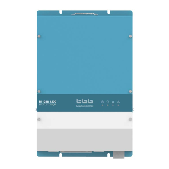
Bi1248‐1200 User Manual 2. Description of main Function 2.1 General Description Bi1248‐1200 is a bi‐directional converter charger for vehicles or boat which has dual battery system installed. It was designed to charge 48Vdc auxiliary battery on a 12Vdc chassis. Due to its bi‐directional design, the 12Vdc load can be powered as it used to be. ... -
Page 7: Features
Bi1248‐1200 User Manual 2.3 Features High Power in‐vehicle charging, max 1.2KWH can be charged per hour. DSP control with fast and sophisticated algorithm Non‐isolation design with max efficiency 94% Alternator Input range 11.6‐16Vdc, standing up to 35Vdc Can be used for Euro6 with smart alternator Multiple battery chemical can be chose including lithium battery TBB premium II multiple stages charging algorithm Built in automatic temperature and voltage compensated charging Thermal controlled fan cooling With built in RS485 and CAN capability Dry contact output, capacity of 250Vac/28Vdc 5A Dry contact input, for external control to power off the device Complete protection against output short circuit, output over current, over/low voltage, over temperature and output reverse polarity ... -
Page 8: Structure
Bi1248‐1200 User Manual 3. Structure 3.1 Dimension 306.3 282.8 301.6 291.6 ... -
Page 9: Installation Requirements
Bi1248‐1200 User Manual 4. Preparation 4.1 Inspection After unpacking, please check if the unit is damaged during the transportation and there is complete set of accessories. ... -
Page 10: Installation
Bi1248‐1200 User Manual 5. Installation For the user operation safety, cut off the power before installation. ... -
Page 11: Wiring Diagram
Bi1248‐1200 User Manual 5.1 Wiring diagram Figure 5 Schematic diagram of the key components of Bi1248‐1200 wiring compartment Table 4 Key materials specification of wiring compartment Name Description . ... - Page 12 ON Smart generator ‐ Euro 6 OFF,OFF Stand‐alone mode ON,OFF N/A System 4,5 working mode OFF,ON N/A ON,ON N/A Communicatio OFF N/A 6 n protocol standard ON TBB standard 7,8 X,X Reserved, no function now For Euro 6 vehicle with smart alternator, to assure the right charging, it is important to configure the device. ...
- Page 13 Bi1248‐1200 User Manual 5.2 Wiring instruction For the crimp terminal of the 12V cable, use the M8 nut with a flat washer and a spring washer. ...
-
Page 14: Com Terminal Definition
Bi1248‐1200 User Manual 5.3 COM terminal definition The COM terminal is for communication signal, voltage sampling signal, and a dry contact signal. The pins are defined as follows. Table 5 Communication terminal definition on BI charger Pin Function Description Diagram No. ... -
Page 15: Users Instructions
Bi1248‐1200 User Manual 6. Users Instructions 6.1 Checking and Power On Please double confirm the alternator voltage matching the input voltage of this device. Wrong voltage might damage the device and it is out of warranty. Please double check the input and output was connected correctly to starter battery and auxiliary battery correctly. ... -
Page 16: Indicator Definition
Bi1248‐1200 User Manual 6.2 Indicator definition Figure 6 Bi1248‐1200 indicator film diagram Table 6 Bi1248‐1200 indicator status description Indicator Indicator Identificatio Color Status Description Name n ... - Page 17 Bi1248‐1200 User Manual 6.3 Auxiliary battery charging curve Charging curve Figure 7 TBB standard battery charging curve Battery types and bulk charging & absorption charging voltage Table 8 Service battery types and bulk charging & absorption charging voltage Absorption charging No. Battery types Bulk charging voltage voltage 1 AGM 57.6V 54V ...
-
Page 18: Operating Temperature Derating Curve
Bi1248‐1200 User Manual 6.6 Operating temperature de‐rating curve This device has built in intelligent temperature control and will reduce its output power in case of high working temperature reached. Load Rate (%) ℃ Internal Temperature( ) Figure 8 Bi1248‐1200 internal temperature and output power derating curve ... -
Page 19: Technical Data Sheet
Booster mode Stepdown mode Input voltage 11.6~16V 42~60V Max Input current 100A Nominal 48Vdc, adaptive Output voltage 13Vdc charging Charging TBB premium II multi stage Constant Voltage algorithm Electrical Max Output 100A current Efficiency Max>94%,Full load>91% Standby <2mA consumption alarm: 14.9Vdc,protection: Input overvoltage alarm: 59.6V,protection: 60Vdc... - Page 20 Bi1248‐1200 User Manual TBB Power Co., Ltd Web: www.tbbpower.com Tel: +86‐592‐5212299 Fax: +86‐592‐5796070 Email: service@tbbpower.com ...
Need help?
Do you have a question about the Bi1248-1200 and is the answer not in the manual?
Questions and answers