
Subscribe to Our Youtube Channel
Related Manuals for Gigabyte GA-6VEM


Summary of Contents for Gigabyte GA-6VEM
- Page 1 GA-6VEM Series Socket 370 Processor Motherboard USER’ S MANUAL Socket 370 Processor Motherboard Rev. 1006 12ME-6VEM-1006...
-
Page 2: Table Of Contents
Item Checklist ...4 WARNING! ...5 Chapter 1 Introduction ...6 Summary of Features ... 6 GA-6VEM Series Motherboard Layout ... 8 Chapter 2 Hardware Installation Process ...9 Step 1: Install the Central Processing Unit (CPU) ... 10 Step1-1: CPU Speed Setup ... 10 Step1-2: CPU Installation ... - Page 3 Power Management Setup ... 40 PnP/PCI Configurations ... 45 PC Health Status ... 47 Frequency/Voltage Control ... 49 Load Fail-Safe Defaults ... 50 Load Optimized Defaults ... 51 Set Supervisor/User Password ... 52 Save & Exit Setup ... 53 Exit Without Saving ... 54 Chapter 4 Technical Reference ...
-
Page 4: Revision History
GA-6VEM Series Motherboard Revision History Revision Initial release of the GA-6VEM Series motherboard user's manual. Second release of the GA-6VEM Series motherboard user's manual. Third release of the GA-6VEM Series motherboard user's manual. Fourth release of the GA-6VEM Series motherboard user's manual. -
Page 5: Warning
WARNING! Computer motherboards and expansion cards contain very delicate Integrated Circuit (IC) chips. To protect them against damage from static electricity, you should follow some precautions whenever you work on your computer. Unplug your computer when working on the inside. -
Page 6: Chapter 1 Introduction
Chapter 1 Introduction Summary of Features Form Factor — 24.4cm x 19.5cm Micro ATX size form factor, 4 layers PCB. Motherboard — GA-6VEM Series Motherboard GA-6VEM and GA-6VEML — Socket 370 processor supports all new Pentium package) supports Celeron processors in FC-PGA package supports 66/100/133MHz system bus frequency —... - Page 7 Hardware Monitor — CPU/System Fan Revolution detect — CPU/System temperature detect — System Voltage Detect On-Board Sound — AC97 CODEC — Line In/Line Out/Mic In/CD In/Game Port On-Board LAN — Build in RTL8100L Chipset* On-Board VGA — Build in Trident Blade 3D/Pro Media in VT8601T PS/2 Connector —...
-
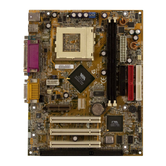
Page 8: Ga-6Vem Series Motherboard Layout
GA-6VEM Series Motherboard GA-6VEM Series Motherboard Layout "*" Only for GA-6VEML. -
Page 9: Chapter 2 Hardware Installation Process
Chapter 2 Hardware Installation Process To set up your computer, you must complete the following setups: Step 1- Set Dip Switch Step 2- Install the Central Processing Unit (CPU) Step 3- Install memory modules Step 4- Install expansion cards Step 5- Connect ribbon cables, cabinet wires, and power supply Step 6- Setup BIOS software Step 7- Install supporting software tools Step 2... -
Page 10: Step 1: Install The Central Processing Unit (Cpu)
GA-6VEM Series Motherboard Step 1: Install the Central Processing Unit (CPU) Step1-1: CPU Speed Setup The system bus frequency can be switched at 66/100/133MHz by BIOS. The clock ratio can be switched by adjusting CLK_RATIO(SW1). (The external frequency depend on CPU .) -
Page 11: Step1-2: Cpu Installation
Step1-2: CPU Installation For example: The newest Pentium III processor (FC-PGA2 package). CPU Top View Socket Actuation Lever 1. Pull up the CPU socket level and up to 90-degree angle. M Please make sure the CPU type is supported by the motherboard. M If you do not match the CPU socket Pin 1 and CPU cut edge well, it will cause improper installation. -
Page 12: Step1-3:Cpu Heat Sink Installation
GA-6VEM Series Motherboard Step1-3:CPU Heat Sink Installation 1. Press down the CPU socket lever and finish CPU installation. 3. Fasten the heatsink supporting-base onto the CPU socket on the main- board. M Please use Intel approved cooling fan. M We recommend you to apply the thermal paste to provide better heat conduction between your CPU and heatsink. -
Page 13: Step 2: Install Memory Modules
Step 2: Install memory modules The motherboard has 2 dual in-line memory module (DIMM) sockets support 4 banks. The BIOS will automatically detects memory type and size. To install the memory module, just push it vertically into the DIMM Sl o t .The DIMM module can only fit in one di r ection due to the two notch. Memory size can vary between sockets. -
Page 14: Step 3: Install Expansion Cards
GA-6VEM Series Motherboard Step 3: Install expansion cards 1. Read the related expansion card’ s instruction document before install the expansion card into the computer. 2. Remove your computer’ s chassis cover, necessary screws and slot bracket from the computer. -
Page 15: Step 4: Connect Ribbon Cables, Cabinet Wires, And Power Supply
Step 4: Connect ribbon cables, cabinet wires, and power supply Step4-1:I/O Back Panel Introduction u PS/2 Keyboard and PS/2 Mouse Connector PS/2 Mouse Connector (6 pin Female) PS/2 Keyboard Connector (6 pin Female) v USB & LAN Connector LAN* USB 0 USB 1 "*"... -
Page 16: Audio Connectors
GA-6VEM Series Motherboard w Parallel Port , Serial Port and VGA Port (LPT/COMA/VGA) Parallel Port (25 pin Female) COMA Serial Port VGA Port (9 pin Male) (15 pin Female) x Game /MIDI Ports Joystick/ MIDI (15 pin Female) y Audio Connectors... -
Page 17: Step4-2: Connectors Introduction
Step4-2: Connectors Introduction A) ATXPWR B) JP10 C) SYS FAN D) Floppy/IDE1/IDE2 E) J7 F) LAN WAKE UP G) IR Hardw are Installation Process H) USB2 I) BATTERY J) CD_IN K) CPU FAN L) COMB M) FRONT AUDIO N) USB_VS... - Page 18 GA-6VEM Series Motherboard K) CPU_FAN (CPU_FAN Connector) Ø The CPU fan connector supports Max. current up to 600 mA . A) ATX PWR (ATX Power) +12V 5V SB (Stand by +5V) Power Good 3.3V 3.3V Ø AC power cord should only be connected to your power supply unit after ATX power cable and other related devices are firmly connected to the mainboard.
- Page 19 D) Floppy / IDE1 / IDE2 M ) Front Audio Connector There are two types of Front Audio connector, please refer to the tables below before you install. Type 1 Hardw are Installation Process G) IR Ø Be careful with the polarity of the IR connector while you connect the IR.
- Page 20 GA-6VEM Series Motherboard H) USB2 I) Battery CAUTION v Danger of explosion if battery is incorrectly replaced. v Replace only with the same or equivalent type recommended by the manufacturer. v Dispose of used batteries according to the manufacturer’ s instructions.
- Page 21 E) J7 (2x11 pins jumper) GN (Green Switch) GD (Green LED) HD (IDE Hard Disk Active LED) Pin 1: LED anode(+) SPK (Speaker Connector) RE (Reset Switch) P+P-P-(Power LED) PW (Soft Power Connector) Ø Please connect t h e power LED, PC speaker, reset switch and power switch etc of your chassis front panel to the front panel jumper according to the pin assignment above.
-
Page 22: Chapter 3 Bios Setup
GA-6VEM Series Motherboard Chapter 3 BIOS Setup BIOS Setup is an overview of the BIOS Setup Program. The program that allows users to modify the basic system configuration. This type of information is stored in battery-backed CMOS RAM so that it retains the Setup information when the power is turned off. -
Page 23: The Main Menu (For Example: Bios Ver. :F1)
GETTING HELP Main Menu The on-line description of the highlighted setup function is displayed at the bottom of the screen. Status Page Setup Menu / Option Page Setup Menu Press F1 to pop up a small help window that describes the appropriate keys to use and the possible selections for the highlighted item. -
Page 24: Integrated Peripherals
GA-6VEM Series Motherboard Integrated Peripherals This setup page includes all onboard peripherals. Power Manag ement Setup This setup page includes all the items of Green function features. PnP/PCI Configurations This setup page includes all the configurations of PCI & PnP ISA resources. -
Page 25: Standard Cmos Features
Standard CMOS Features CMOS Setup Utility -Copy right (C) 1984-2001 Aw ard Softw are Standard CMOS Features Date (mm:dd:y y ) Time (hh:mm:ss) }IDE Primary Master }IDE Primary Slav e }IDE Secondary Master }IDE Secondary Slav e Driv e A Driv e B Floppy 3 Mode Support Video... - Page 26 GA-6VEM Series Motherboard C Time The times format in <hour> <minute> <second>. The time is calculated base on the 24-hour military-time clock. For example, 1 p.m. is 13:00:00. C IDE Primary Master, Slave / Secondary Master, Slave The category identifies the ty pes of hard disk from driv e C to F that has been installed in the computer.
- Page 27 C Floppy 3 Mode Support (for J apan Area) Normal Floppy Driv e. (Default v alue) 8Disabled 8Driv e A Driv e A is 3 mode Floppy Driv e. 8Driv e B Driv e B is 3 mode Floppy Driv e. Driv e A &...
-
Page 28: Base Memory
GA-6VEM Series Motherboard Memory The category is display-onl y which is determi n ed by POST (Power On Self Test) of the BIOS. Base Memory The POST of the BIOS will determine the amount of base (or conventional) memory installed in the system. -
Page 29: Advanced Bios Features
Advanced BIOS Features CMOS Setup Utility -Copy right (C) 1984-2001 Aw ard Softw are Adv anced BIOS Features BIOS Flash Protection Processor Serial Number First Boot Dev ice Second Boot Dev ice Third Boot Dev ice Boot Up Floppy Seek Boot Up Num-Lock Passw ord Check MPS Version Control For OS... -
Page 30: Password Check
GA-6VEM Series Motherboard Select y our boot dev ice priority by CDROM. 8CDROM Select y our boot dev ice priority by ZIP. 8ZIP Select y our boot dev ice priority by USB-FDD. 8USB-FDD Select y our boot dev ice priority by USB-ZIP. -
Page 31: Mps Version Control For Os
C MPS Version Control For OS (Support Multi Processor Specification revision 1.4) Support MPS Version 1.4 . (Default Value) 81.4 Support MPS Version 1.1. 81.1 CHDD S.M.A.R.T. Capability Enabled HDD S.M.A.R.T. Capability . 8Enabled Disabled HDD S.M.A.R.T. Capability . (Default v alue) 8Disabled CDelay For HDD (Secs) Set delay for HDD from 0secs to 15 secs. -
Page 32: Advanced Chipset Features
GA-6VEM Series Motherboard Advanced Chipset Features CMOS Setup Utility -Copy right (C) 1984-2001 Aw ard Softw are Adv anced Chipset Features Bank 0/1 DRAM Timing Bank 2/3 DRAM Timing SDRAM Cy cle Length DRAM Clock AGP Aperture Size OnChip USB... -
Page 33: Sdram Cas Latency
C SDRAM CAS Latency Set SDRAM CAS Latency is 3SCLKS.(Default Value) Set SDRAM CAS Latency is 2SCLKS. C DRAM Clock 8Host CLK Set DRAM CLK equal to Host CLK. (Default Value) 8HCLK-33M Set DRAM CLK to HCLK-33M. C AGP Aperture Size Set AGP Aperture Size to 4MB. -
Page 34: Pci Delay Transaction
GA-6VEM Series Motherboard C USB Mouse Support Enabled USB Mouse Support 8Enabled 8Disabled Disabled USB Mouse Support (Default Value) C OnChip Sound Enabled Onchip Sound. (Default Value) 8Auto 8Disabled Disabled Onchip Sound. C OnChip Modem Enabled Onchip Modem. (Default Value) 8Auto 8Disabled Disabled Onchip Modem. -
Page 35: Integrated Peripherals
Integrated Peripherals CMOS Setup Utility -Copy right (C) 1984-2001 Aw ard Softw are Integrated Peripherals IDE1 Conductor Cable IDE2 Conductor Cable On-Chip IDE Channel 0 On-Chip IDE Channel 1 Init Display First Enhance ATAPI Performance Onboard FDD Controller Onboard Serial Port A Onboard Serial Port B Serial Port B Mode ø... -
Page 36: Init Display First
GA-6VEM Series Motherboard C IDE 1 Conductor Cable Set IDE 1 Conductor cable to auto.(Default v alue) 8Auto Set IDE 1 Conductor cable to ATA66/100. 8ATA66/100 IDE 1 Conductor cable to ATA33. 8ATA33 C IDE 2 Conductor Cable IDE 2 Conductor cable to auto.(Default v alue) 8Auto IDE 2 Conductor cable to ATA66/100. -
Page 37: Onboard Parallel Port
C Onboard Serial Port A BIOS w ill automatically setup the port A address. 8Auto Enable onboard Serial port A and address is 3F8. (Default Value) 83F8/IRQ4 Enable onboard Serial port A and address is 2F8. 82F8/IRQ3 Enable onboard Serial port A and address is 3E8. 83E8/IRQ4 Enable onboard Serial port A and address is 2E8. - Page 38 GA-6VEM Series Motherboard C Onboard Parallel Mode Using Parallel port as Normal. 8Normal Using Parallel port as Enhanced Parallel Port. 8EPP Using Parallel port as Ex tended Capabilities Port. (Default Value) 8ECP Using Parallel port as ECP & EPP mode.
- Page 39 C SB IRQ Select Set SB IRQ is IRQ5. (Default Value) 8IRQ5 Set SB IRQ is IRQ7. 8IRQ7 Set SB IRQ is IRQ9. 8IRQ9 Set SB IRQ is IRQ10. 8IRQ10 C SB DMA Select Set SB DMA is DMA0. 8DMA0 Set SB DMA is DMA1.(Default Value) 8DMA1 Set SB DMA is DMA2.
-
Page 40: Power Management Setup
GA-6VEM Series Motherboard Power Management Setup CMOS Setup Utility -Copy right (C) 1984-2001 Aw ard Softw are Pow er Management Setup 4Pow er Management ACPI Suspend Ty pe MODEM Use IRQ Soft-Off by PWRBTN Sy stem After AC Back 4Wake Up Ev ents... -
Page 41: Acpi Suspend Type
CMOS Setup Utility -Copy right (C) 1984-2001 Aw ard Softw are USB Resume from S3/S4/S5 LPT & COM HDD & FDD PCI Master PME Ev ent Wake Up ModemRingOn/WakeOnLan RTC Alarm by Resume ø Date(of Month) Alarm ø Time(hh:mm:ss) Alarm higf: Mov e Enter:Select +/-/PU/PD:Value F10:Sav e ESC:Ex it F1:General Help F5:Prev ious Values F6:Fail-Safe Defaults F7:Optimized Defaults Figure 6-2: Pow er Management Setup... -
Page 42: Power Management
GA-6VEM Series Motherboard C Soft-off by Power Button 8Instant off Soft sw itch ON/OFF for Pow er Button. (Default Value) 8Delay -4Sec Soft sw itch ON 4 Sec for Pow er off. C System After AC Back 8Last State Set Last state to sy stem after AC back. - Page 43 C VGA Disable monitor VGA activ ity. (Default Value) 8OFF Enable monitor VGA activ ity . C LPT & COM Enabled LPT/COM Ports Ac tiv ity. (Default Value) 8LPT/COM Normal Operation. 8NONE Enabled LPT Ports Activ ity . 8LPT Enabled COM Ports Activ ity . 8COM C HDD &...
- Page 44 GA-6VEM Series Motherboard C RTC Alarm by Resume You can set "RTC Alarm Resume" item to enabled and key in Data/time to pow er on sy stem. Disable this function. (Default Value) 8Disabled Enable alarm function to POWER ON sy stem.
-
Page 45: Pnp/Pci Configurations
PnP/PCI Configurations CMOS Setup Utility -Copy right (C) 1984-2001 Aw ard Softw are PnP/PCI Configurations Reset Configuration Data Resources Controlled By øIRQ Resources øDMA Resources PCI1 IRQ Assignment PCI2 IRQ Assignment PCI3 IRQ Assignment higf: Mov e Enter:Select +/-/PU/PD:Value F10:Sav e ESC:Ex it F1:General Help F5:Prev ious Values F6:Fail-Safe Defaults F7:Optimized Defaults C Reset Config uration Data Disabled this function. - Page 46 GA-6VEM Series Motherboard C DMA Resources ( 0,1,3,5,6,7 ) 8PCI/ISA PnP The resource is used by PCI dev ice. 8Legacy ISA Set the resource to reserv ed. C PCI1 IRQ Assignment Auto assign IRQ to PCI 1. (Default v alue) 8Auto Set 3,4,5,7,9,10,11,12,14,15 to PCI1.
-
Page 47: Pc Health Status
PC Health Status CMOS Setup Utility -Copy right (C) 1984-2001 Aw ard Softw are PC Health Status CPU Warning Temperature CPU Fan Warning Sy stem Fan Warning Current CPU Temp. Current Sy stem Temp. Current CPU Fan Speed Current Sy stem Fan speed Vcore 3.3V higf: Mov e Enter:Select +/-/PU/PD:Value F10:Sav e ESC:Ex it F1:General Help... - Page 48 GA-6VEM Series Motherboard C Current CPU / System Fan Speed (RPM) 8Detect Fan speed status automatically . C Current Voltage (V) VCORE / 3.3V / 5 V / 12V 8Detect sy stem’ s v oltage status automatically .
-
Page 49: Frequency/Voltage Control
Frequency/Voltage Control CMOS Setup Utility -Copy right (C) 1984-2001 Aw ard Softw are Frequency /Voltage Control CPU Host Clock (CPU/PCI) higf: Mov e Enter:Select +/-/PU/PD:Value F10:Sav e ESC:Ex it F1:General Help F5:Prev ious Values F6:Fail-Safe Defaults F7:Optimized Defaults Figure 9: Frequency /Voltage Control C CPU Host Clock (CPU/PCI) Set Default Value . -
Page 50: Load Fail-Safe Defaults
GA-6VEM Series Motherboard Load Fail-Safe Defaults CMOS Setup Utility -Copy right (C) 1984-2001 Aw ard Softw are }Standard CMOS Features }Adv anced BI O S Features }Adv anced Chi p set Features }Integrated Peripherals }Pow er Management Setup Load Fail-Safe Defaults? (Y/N)?Y... -
Page 51: Load Optimized Defaults
Load Optimized Defaults CMOS Setup Utility -Copy right (C) 1984-2001 Aw ard Softw are }Standard CMOS Features }Adv anced BI O S Features }Adv anced Chi p set Features }Integrated Peripherals }Pow er Management Setup }PnP/PCI Configurations Load Optimized Defaults? (Y/N)?Y }PC Healt h Status ESC:Quit F10:Sav e &... -
Page 52: Set Supervisor/User Password
GA-6VEM Series Motherboard Set Supervisor/User Password CMOS Setup Utility -Copy right (C) 1984-2001 Aw ard Softw are }Standard CMOS Features }Adv anced BI O S Features }Adv anced Chi p set Features }Integrated Peripherals }Pow er Management Setup }PnP/PCI Configurations... -
Page 53: Save & Exit Setup
Save & Exit Setup CMOS Setup Utility -Copy right (C) 1984-2001 Aw ard Softw are }Standard CMOS Features }Adv anced BI O S Features }Adv anced Chi p set Features }Integrated Peripherals }Pow er Management Setup }PnP/PCI Configurations Save to CMOS and EXIT (Y/N)? Y }PC Healt h Status ESC:Quit F10:Sav e &... -
Page 54: Exit Without Saving
GA-6VEM Series Motherboard Exit Without Saving CMOS Setup Utility -Copy right (C) 1984-2001 Aw ard Softw are }Standard CMOS Features }Adv anced BI O S Features }Adv anced Chi p set Features }Integrated Peripherals }Pow er Management Setup }PnP/PCI Configurations... -
Page 55: Chapter 4 Technical Reference
Chapter 4 Technical Reference Block Diagram 66/100/133MHz On Chip VGA 3 PCI RTL8100(B)L* PCI BUS ISA BUS PCICLK 1 AMR (33MHz) AC97 CODEC 1 ISA "*" Only for GA-6VEML. 66/100/133MHz Socket 370 Host Bus 100/133 MHz VT8601T 33 MHz 14.318 MHz 48 MHz VT82C686B 4 USB... -
Page 56: Bios Introduction
BIOS directly. Or you may want to keep a backup for your current BIOS, just choose “ Save Current BIOS” to save it first. You make a wise choice to use Gigabyte, and @BIOS update your BIOS smartly. You are now worry free from updating wrong BIOS, and capable to maintain and manage your BIOS easily. -
Page 57: Easy Tuneiii Tm Introduction
Now everything is different because of a Windows overdrive utility EasyTuneIII— announced by Gigabyte. This utility has totally changed the gaming rule of “ overdrive” . This is the first overdrive utility suitable for both normal and power users. Users can choose either “ Easy Mode” or “ Advanced Mode”... -
Page 58: Chapter 5 Appendix
GA-6VEM Series Motherboard Chapter 5 Appendix Picture below are shown in Windows ME (VUCD driver version 1.81) Appendix A: VIA 8601T Chipset Driver Installation A. Windows 9x/ME/2000/XP INF Update Utility: Insert the driver CD-title that came with your motherboard into your CD-ROM driver, the driver CD-title will auto start and show the installation guide. - Page 59 Appendix 5.Click "Next". 6.Click "Next". 7.Click "Finish" to restart computer.
- Page 60 GA-6VEM Series Motherboard Appendix B: VGA Utilities Installation Insert the driver CD-title that came with your motherboard into your CD-ROM driver, the driver CD-title will auto start and show the installation guide. If not, please double click the CD-ROM device icon in "My computer", and execute the setup.exe.
- Page 61 Appendix Appendix C: AC97 Sound Chipset Drvier Installation Insert the driver CD-title that came with your motherboard into your CD-ROM driver, the driver CD-title will auto start and show the installation guide. If not, please double click the CD-ROM device icon in "My computer", and execute the setup.exe.
- Page 62 GA-6VEM Series Motherboard Appendix D: RealTek 8139/8130/8100 Network Driver (For GA-6VEML Only) "RealTek 8139/8130/8100 Network Driver" under Windows ME will auto install. If you would like to install LAN driver, please refer to attached README.txt file for detail instruction. Please install the driver through CD-ROM by the path D:\Network\Rtl (This manual assumes that your CD-ROM device drive letter is D:).
- Page 63 Appendix E: Acronyms Acronyms Meaning ACPI Advanced Configuration and Power Interface AP M Advanced Power Management Accelerated Graphics Port Audio Modem Riser Advanced Communications Riser BIOS Basic Input / Output System C P U Central Processing Unit CMOS Complementary Metal Oxide Semiconductor CRIMM Continuity RIMM Communication and Networking Riser...
- Page 64 GA-6VEM Series Motherboard Acronyms Meaning Logical Block Addressing Light Emitting Diode MH z Megahertz MIDI Musical Interface Digital Interface Memory Translator Hub Memory Protocol Translator Network Interface Card Operating System Original Equipment Manufacturer PCI A.G.P. Controller POST Power-On Self Test...
- Page 65 Technical Support/RMA Sheet Customer/Country: Contact Person: E-mail Add. : Model name/Lot Number: BIOS version: O.S./A.S.: Hardware Mfs. Model name Configuration C P U Memory Brand Video Card Audio Card CD-ROM / DVD-ROM Modem Network AMR / CNR Keyboard Mouse Power supply Other Device Problem Description: Company:...
-
Page 66: Declaration Of Conformity
(2) this device must accept any inference received, including that may cause undesired operation. Representative Person’s Name: Signature: Eric Lu Date: G.B.T. INC. 18305 Valley Blvd., Suite#A LA Puent, CA 91744 (818) 854-9338/ (818) 854-9339 Motherboard GA-6VEM/GA-6VEML ERIC LU Sep. 9, 2001... - Page 67 Safety of household and similar electrical appliances (St a mp) We, Manufacturer/Importer (full address) declare that the product Mother Board GA-6VEM/GA-6VEML is in conformity with o EN 61000-3-2* Disturbances in supply systems cause T EN 60555-2 by household appliances and similar electrical equipment “Harmonics”...
Need help?
Do you have a question about the GA-6VEM and is the answer not in the manual?
Questions and answers