Table of Contents
Advertisement
Revision History
? The author assumes no responsibility for any
errors or omissions that may appear in this
document nor does the author make a commit
ment to up date the information contained
herein.
? Third-party brands and names are the property
of their respective owners.
? Please do not remove any labels on
motherboard, this may void the warranty of
this motherboard.
? Due to rapid change in technology, some of the
specifications might be out of date before
pwblicution of this booklet.
Advertisement
Table of Contents

Related Manuals for Gigabyte GA-6IEM


Summary of Contents for Gigabyte GA-6IEM
- Page 1 Revision History ? The author assumes no responsibility for any errors or omissions that may appear in this document nor does the author make a commit ment to up date the information contained herein. ? Third-party brands and names are the property of their respective owners.
- Page 3 Declaration of Conformity Rex Li n...
-
Page 4: Declaration Of Conformity
(2) this device must accept any inference received, including that may cause undesired operation. Representative Person’ s Name: Signature: Eric Lu Dat e: G.B.T. INC. 18305 Valley Blvd., Suite#A LA Puent, CA 91744 (818) 854-9338/ (818) 854-9339 Mother boar d GA-6IEM /GA-6IEML ERIC LU October 19,2001... - Page 5 GA-6IEM(L) Series Socket 370 Processor Motherboard USER’S MANUAL Socket 370 Processor Motherboard Rev. 1.1 First Edition 12ME-6IEM-1101...
-
Page 6: Table Of Contents
Item Checklist ...4 WARNING! ...5 Chapter 1 Introduction ...6 Features Summary... 6 GA-6IEM Series Motherboard Layout ... 8 Chapter 2 Hardware Installation Process ...9 Step 1: Install the Central Processing Unit (CPU) ... 10 Step1-1: CPU Installation ... 10 Step1-2: CPU Heat Sink Installation ... 11 Step 2: Install memory modules ... - Page 7 Power Management Setup ... 48 PnP/PCI Configurations ... 52 PC Health Status ... 54 Frequency/Voltage Control ... 56 Load Fail-Safe Defaults ... 58 Load Optimized Defaults ... 59 Set Supervisor/User Password ... 60 Save & Exit Setup ... 61 Exit Without Saving ... 62 Chapter 4 Technical Reference ...
-
Page 8: Revision History
GA-6IEM Series Motherboard Revision History Revision Revision Note Date Initial release of the GA-6IEM Series motherboard user's manual. Nov. 2001 Item Checklist ? The GA-6IEM Series motherboard ? IDE cable x 1/ Floppy cable x 1 ? CD for motherboard driver & utility (IUCD) ? GA-6IEM Series user’s manual... -
Page 9: Warning
WARNING! Computer motherboards and expansion cards contain very delicate Integrated Circuit (IC) chips. To protect them against damage from static electricity, you should follow some precautions whenever you work on your computer. Unplug your computer when working on the inside. -
Page 10: Chapter 1 Introduction
Chapter 1 Introduction Features Summary Form Factor ? 24.4cm x 20.2cm Micro ATX size form factor, 4 layers PCB. Motherboard ? GA-6IEM Series Motherboard GA-6IEM and GA-6IEML ? Socket 370 processor supports Pentium & FC-PGA2 package) supports Celeron Tualatin processors (FC-PGA &... - Page 11 ? 1 SCR(Smart card Reader) Hardware Monitor ? CPU/System Fan Revolution detect ? CPU/System temperature detect ? System Voltage Detect On-Board Sound ? AC97 CODEC ? Line In/Line Out/Mic In/CD In/Game Port/SPDIF/Front Audio Header On-Board LAN ? Build in Kinnereth 82562ET* On-Board VGA ? Build in FW82815 PS/2 Connector...
-
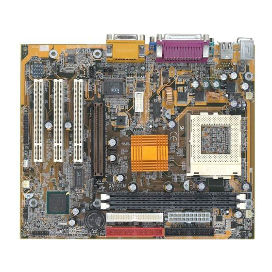
Page 12: Ga-6Iem Series Motherboard Layout
GA-6IEM Series Motherboard GA-6IEM Series Motherboard Layout KB_MS JP34* JP41 COM B AC97 BIOS * For GA-6IEML only. SOCKET 370 GA-6IEM(L) 82815 BATTERY PCI1 PCI2 ICH2 PCI3 JP32 JP13 JP22... -
Page 13: Chapter 2 Hardware Installation Process
Chapter 2 Hardware Installation Process To set up your computer, you must complete the following steps: Step 1- Install the Central Processing Unit (CPU) Step 2- Install memory modules Step 3- Install expansion cards Step 4- Connect ribbon cables, cabinet wires, and power supply Step 5- Setup BIOS software Step 6- Install supporting software tools Hardw are Installation Process... -
Page 14: Step1-1: Cpu Installation
GA-6IEM Series Motherboard Step1-1: CPU Installation For example: The newest Pentium III processor (FC-PGA2 package). CPU Top View Socket Actuation Lever 1. Pull up the CPU socket lever and up to 90-degree angle. ? Please make sure the CPU type is supported by the motherboard. -
Page 15: Step1-2:Cpu Heat Sink Installation
Step1-2:CPU Heat Sink Installation 1. Press down the CPU socket lever and finish CPU installation. 3. Fasten the heatsink supporting-base onto the CPU socket on the main- board. ? Please use Intel approved cooling fan. ? We recommend you to apply the thermal paste to provide better heat conduction between your CPU and heatsink. -
Page 16: Step 2: Install Memory Modules
GA-6IEM Series Motherboard Step 2: Install memory modules The motherboard has 2 dual in-line memory module (DIMM) sockets support 4 banks. The BIOS will automatically detects memory type and size. To install the memory module, just push it vertically into the DIMM Sl o t .The DIMM module can only fit in one di r ection due to the two notch. -
Page 17: Step 3: Install Expansion Cards
Step 3: Install expansion cards 1. Read the related expansion card’s instruction document before install the expansion card into the computer. 2. Remove your computer’s chassis cover, screws and slot bracket from the computer. 3. Press the expansion card firmly into expansion slot in motherboard. 4. -
Page 18: Step 4: Connect Ribbon Cables, Cabinet Wires, And Power Supply
GA-6IEM Series Motherboard Step 4: Connect ribbon cables, cabinet wires, and power supply Step4-1:I/O Back Panel Introduction ? PS/2 Keyboard and PS/2 Mouse Connector PS/2 Mouse Connector (6 pin Female) PS/2 Keyboard Connector (6 pin Female) ? USB & LAN Connector... -
Page 19: Audio Connectors
? Parallel Port , Serial Port and VGA Port (LPT/COMA/VGA) Parallel Port (25 pin Female) COMA Serial Port VGA Port (9 pin Male) (15 pin Female) ? Game /MIDI Ports Joystick/ MIDI (15 pin Female) ? Audio Connectors MIC In Line Out Line In Hardw are Installation Process... -
Page 20: Step4-2: Connectors Introduction
GA-6IEM Series Motherboard Step4-2: Connectors Introduction A) J2 B) LED 2 C) ATX PWR D) Floppy E) IDE/IDE2 F) BATTERY G) F_PANEL H) JP32 I) J14 J) J12 K) JP13 L) J16 M) JP22 N) J5 O) JP44 P) JP41... - Page 21 A) J2 (Power_FAN Connector) S) J1 (CPU_FAN Connector) C) ATX PWR (ATX Power) +12V 5V SB (Stand by +5V) Power Good 3.3V 3.3V Hardw are Installation Process I) J14 (SYS_FAN Connector) ? Please note, a proper installation of the CPU cooleris essential to prevent the CPU from run ning under abnormal condition or damaged by overheating.The CPU fan connector supports...
- Page 22 GA-6IEM Series Motherboard J) J12 (Wake on LAN) +5V SB Signal O)JP44 (SPDIF) SPDIF Out SPDIF P)JP41 (F_AUDIO Connector) Incase speaker (R) +12V Front Audio (R) Front Audio (L) ? The SPDIF output is capable of providing digital audio to external speakers or com pressed AC3 data to an external Dolby Digital Decoder.
- Page 23 Hardw are Installation Process D ) Floppy Connector E) IDE1 / IDE2 Connector Q) CN10 (COM B)
- Page 24 GA-6IEM Series Motherboard H) JP32 (Front USB Connector) B) LED 2 (STR/DIMM LED) N) J5 (CD_IN ) R) JP34 (Onboard LAN Function)* 1-2 close: Enable(Default) 2-3 close: Disable * For GA-6IEML only. ? Be careful with the polarity of the front panel USB connector.
- Page 25 K) JP13 (IR/CIR ) L) J16 (Smart Card Reader Header) M) JP22 (CASE OPEN) CASE OPEN Hardw are Installation Process ? Make sure the pin 1 on the IR device is aling with pin one the connector. To enable the IR/CIR function on the board, you are required to purchase an option IR/ CIR module.
- Page 26 GA-6IEM Series Motherboard G) F_PANEL (2x7 pins jumper) HD (IDE Hard Disk Active LED) Pin 1: LED anode(+) Pin 2: LED cathode(-) SPK (Speaker Connector) Pin 1: VCC(+) Pin 2- Pin 3: NC Pin 4: Data(-) RE (Reset Switch) Open: Normal Operation...
-
Page 27: Chapter 3 Bios Setup
Chapter 3 BIOS Setup BIOS Setup is an overview of the BIOS Setup Program. The program that allows users to modify the basic system configuration. This type of information is stored in battery-backed CMOS RAM so that it retains the Setup information when the power is turned off. ENTERING SETUP Power ON the computer and press <Del>... -
Page 28: The Main Menu (For Example: Bios Ver. :F3D)
GA-6IEM Series Motherboard GETTING HELP Main Menu The on-line description of the highlighted setup function is displayed at the bottom of the screen. Status Page Setup Menu / Option Page Setup Menu Press F1 to pop up a small help window that describes the appropriate keys to use and the possible selections for the highlighted item. -
Page 29: Advanced Chipset Features
Advanced Chipset Features This setup page includes all the items of chipset special features. Integrated Peripherals This setup page includes all onboard peripherals. Power Management Setup This setup page includes all the items of Green function features. PnP/PCI Configurations This setup page includes all the configurations of PCI & PnP ISA resources. PC Health Status This setup page is the System auto detect T emperature, voltage, fan, speed. -
Page 30: Standard Cmos Features
GA-6IEM Series Motherboard Standard CMOS Features CMOS Setup Utility-Copyright (C) 1984-2001 Award Software Standard CMOS Features Date (mm:dd:yy) Time (hh:mm:ss) ?IDE Primary Master ?IDE Primary Slave ?IDE Secondary Master ?IDE Secondary Slave Drive A Drive B Floppy 3 Mode Support... - Page 31 ? Time The times format in <hour> <minute> <second>. The time is calculated base on the 24-hour military-time clock. For example, 1 p.m. is 13:00:00. ? IDE Primary Master, Slave / Secondary Master, Slave The category identifies the types of hard disk from drive C to F that has been installed in the computer.
- Page 32 GA-6IEM Series Motherboard ? Floppy 3 Mode Support (for Japan Area) Normal Floppy Drive. (Default value) ?Disabled ?Drive A Drive A is 3 mode Floppy Drive. ?Drive B Drive B is 3 mode Floppy Drive. Drive A & B are 3 mode Floppy Drives.
-
Page 33: Base Memory
??Memory The category is display-onl y which is determi n ed by POST (Power On Self T est) of the BIOS. Base Memory The POST of the BIOS will determine the amount of base (or conventional) memory installed in the system. The value of the base memory is typically 512 K for systems with 512 K memory installed on the motherboard, or 640 K for systems with 640 K or more memory installed on the motherboard. -
Page 34: Advanced Bios Features
GA-6IEM Series Motherboard Advanced BIOS Features CMOS Setup Utility-Copyright (C) 1984-2001 Award Software Advanced BIOS Features BIOS Flash Protection Processor Serial Number First Boot Device Second Boot Device Third Boot Device Boot Up Floppy Seek Boot Up Num-Lock Password Check... -
Page 35: Boot Up Numlock
? First / S econd / Third Boot Device Select your boot device priority by Floppy. ?Floppy Select your boot device priority by LS120. ?LS120 Select your boot device priority by HDD-0~3. ?HDD-0~3 Select your boot device priority by SCSI. ?SCSI Select your boot device priority by CDROM. - Page 36 GA-6IEM Series Motherboard ? Passwor d Check Please refer to the detail on P.60 The system can not boot and can not access to Setup page will be denied ?System if the correct password is not entered at the prompt.
-
Page 37: Advanced Chipset Features
Advanced Chipset Features We would not suggest you change the chipset default setting unless you really need it. CMOS Setup Utility-Copyright (C) 1984-2001 Award Software Advanced Chipset Features Top Performance SDRAM Timing Control X SDRAM CAS Latency Time X SDRAM Cycle Time Tras/Trc X SDRAM RAS-to-CAS Delay X SDRAM RAS Precharge Time Delayed Transaction... -
Page 38: Top Performance
GA-6IEM Series Motherboard CMOS Setup Utility-Copyright (C) 1984-2001 Award Software Advanced Chipset Features Buffer Strength Control X SWE#, SCAS#, SRAS, SMAA, SBS X SMD[63:0], SDQM[7:0] X SMAA#[7:4] (Rows 0/1) X SMAB#[7:4] (Rows 2/3) X SMAC#[7:4] (Rows 4/5) X SCS[0]# (Row 0) -
Page 39: Delayed Transaction
? SDRAM CAS Latency Time Set SDRAM CAS Latency to 3 SCLKS.(Default Value) Set SDRAM CAS Latency to 2 SCLKS. ? SDRAM Cycl e Time Tras/Trc Set SDRAM Tras/Trc Cycle time to 7/9 SCLKs. (Default value) ?7/9 Set SDRAM Tras/Trc Cycle time to 5/7 SCLKs. ?5/7 ? SDRAM RAS-to-CAS Delay Set SDRAM RAS-to-CAS delay 3 SCLKs. - Page 40 GA-6IEM Series Motherboard ? Onchip Video Windows Size ?Disabled Disabled this function. Set onchip video size is 64MB. (Default Value) ?64MB ? Buffer Strength Control Set SDRAM Buffer Strength to Auto. (Default value) ?Auto Set SDRAM Buffer Strength to Manual.
- Page 41 ? SMAB#[7:4] (Rows 2/3) Set SMAB#[7:4] (Rows 2/3) to Default. (Default value) ?Default Set SMAB#[7:4] (Rows 2/3) to 2.7x. ?2.7x Set SMAB#[7:4] (Rows 2/3) to 1.7x. ?1.7x Set SMAB#[7:4] (Rows 2/3) to 1.0x. ?1.0x ? SMAC#[7:4] (Rows 4/5) Set SMAC#[7:4] (Rows 4/5) to Default. (Default value) ?Default Set SMAC#[7:4] (Rows 4/5) to 2.7x.
- Page 42 GA-6IEM Series Motherboard ? SCS[3]# (Row 3) Set SCS[3]# (Row 3) to Default. (Default value) ?Default Set SCS[3]# (Row 3) to 1.7x. ?1.7x Set SCS[3]# (Row 3) to 1.0x. ?1.0x ? SCS[4]# (Row 4) Set SCS[4]# (Row 4) to Default. (Default value) ?Default Set SCS[4]# (Row 4) to 1.7x.
- Page 43 ? SCKE[3]# (Row 3) Set SCKE[3]# (Row 3) to Default. (Default value) ?Default Set SCKE[3]# (Row 3) to 2.7x. ?2.7x Set SCKE[3]# (Row 3) to 1.7x. ?1.7x ? SCKE[4]# (Row 4) Set SCKE[4]# (Row 4) to Default. (Default value) ?Default Set SCKE[4]# (Row 4) to 2.7x.
-
Page 44: Integrated Peripherals
GA-6IEM Series Motherboard Integrated Peripherals CMOS Setup Utility-Copyright (C) 1984-2001 Award Software Integrated Peripherals On-Chip Primary PCI IDE On-Chip Secondary PCI IDE IDE Primary Master PIO IDE Primary Slave PIO IDE Secondary Master PIO IDE Secondary Slave PIO IDE Primary Master UDMA... - Page 45 CMOS Setup Utility-Copyright (C) 1984-2001 Award Software Integrated Peripherals ?UR2 Duplex Mode Onboard Parallel Port Parallel Port Mode X ECP Mode Use DMA AC BACK Function Game Port Address Midi Port Address Midi Port IRQ CIR Port Address ?CIR Port IRQ ????: Move Enter:Select +/-/PU/PD:Value F10:Save ESC:Exit F1:General Help F5:Previous Values F6:Fail-Safe Defaults F7:Optimized Defaults Figure 5-1: Integrated Peripherals...
- Page 46 GA-6IEM Series Motherboard ? IDE Primary Slave PIO (for onboard IDE 1st channel) BIOS will automatically detect the IDE HDD Accessing mode.(Default value) ?Auto Manually set the IDE Accessing mode. ?Mode0~4 ? IDE Secondary Master PIO (for onboard IDE 2nd channel) BIOS will automatically detect the IDE HDD Accessing mode.(Default value)
-
Page 47: Usb Controller
? IDE1 Conductor Cable Will be automatically detected by BIOS. (Default Value) ?Auto Set IDE1 Conductor Cable to ATA66/100 (Please make sure your IDE device ?ATA66/100 and cable is compatible with ATA66/100). Set IDE1 Conductor Cable to ATA33 (Please make sure your IDE device and ?ATA33 cable is compatible with ATA33). -
Page 48: Ac97 Audio
GA-6IEM Series Motherboard ? AC97 Audio Enable onboard AC'97 audio function. (Default Value) ?Auto Disable this function. ?Disabled ? AC97 Modem BIOS will search MC97 Codec (AMR Modem Card). If found, MC97 function ?Auto will be enabled. If no MC97 Codec found, MC97 function will be disabled. -
Page 49: Uart Mode Select
? Onboard Ser ial Port 1 BIOS will automatically setup the port 1 address. ?Auto Enable onboard Serial port 1 and address is 3F8. (Default value) ?3F8/IRQ4 Enable onboard Serial port 1 and address is 2F8. ?2F8/IRQ3 Enable onboard Serial port 1 and address is 3E8. ?3E8/IRQ4 Enable onboard Serial port 1 and address is 2E8. -
Page 50: Parallel Port Mode
GA-6IEM Series Motherboard ? Onboard Par allel port Enable onboard LPT port and address is 378/IRQ7. (Default Value) ?378/IRQ7 Enable onboard LPT port and address is 278/IRQ5. ?278/IRQ5 Disable onboard LPT port. ?Disabled Enable onboard LPT port and address is 3BC/IRQ7. - Page 51 ?Midi Port IRQ Set 5 for Midi Port IRQ. Set 11 for Midi Port IRQ. (Default Value) ?CIR Port Address Disable this function. (Default Value) ?Disabled Set CIR Port Address to 310. ?310 Set CIR Port Address to 320. ?320 ?CIR Port IRQ Set 5 for CIR Port IRQ.
-
Page 52: Power Management Setup
GA-6IEM Series Motherboard Power Management Setup CMOS Setup Utility-Copyright (C) 1984-2001 Award Software Power Management Setup ACPI Suspend Type USB Device Wake-Up From S3 X Power Management Video Off Method Video Off In Suspend Suspend Type MODEM Use IRQ Suspend Mode... -
Page 53: Acpi Suspend Type
? ACPI Suspend Type Set ACPI Suspend Type to S1/POS (Power On Suspend). (Default value) ?S1(POS) Set ACPI Suspend Type to S3/STR (Suspend To RAM). ?S3(STR) ? USB Device Wake-Up Fr om S3 Enable USB Device Wakeup From S3. ?Enabled Disable USB Device Wakeup From S3. -
Page 54: Modem Use Irq
GA-6IEM Series Motherboard ? MODEM Use IRQ Set MODEM Use IRQ to NA.(Default value) ?N/A Set MODEM Use IRQ to 3. Set MODEM Use IRQ to 4. Set MODEM Use IRQ to 5. Set MODEM Use IRQ to 7. Set MODEM Use IRQ to 9. -
Page 55: Resume By Alarm
? Modem Ring On/Wake On LAN Disable Modem Ring on/wake on Lan function. ?Disabled Enable Modem Ring on/wake on Lan. (Default Value) ?Enabled ? Resume by Alarm You can set "Resume by Alarm" item to enabled and key in Data/time to power on system. Disable this function. -
Page 56: Pnp/Pci Configurations
GA-6IEM Series Motherboard PnP/PCI Configurations CMOS Setup Utility-Copyright (C) 1984-2001 Award Software PnP/PCI Configurations Resources Controlled By X?IRQ Resources PCI1 IRQ Assignment PCI2 IRQ Assignment PCI3 IRQ Assignment ????: Move Enter:Select +/-/PU/PD:Value F10:Save ESC:Exit F1:General Help F5:Previous Values F6:Fail-Safe Defaults F7:Optimized Defaults... - Page 57 ? PCI1 IRQ Assignment Auto assign IRQ to PCI1. (Default value) ?Auto Set IRQ 3,4,5,7,9,10,11,12,14,15 to PCI1. ?3,4,5,7,9.,10,11,12,14,15 ? PCI2 IRQ Assignment Auto assign IRQ to PCI2. (Default value) ?Auto Set IRQ 3,4,5,7,9,10,11,12,14,15 to PCI2. ?3,4,5,7,9.,10,11,12,14,15 ? PCI3 IRQ Assignment Auto assign IRQ to PCI3.
-
Page 58: Pc Health Status
GA-6IEM Series Motherboard PC Health Status CMOS Setup Utility-Copyright (C) 1984-2001 Award Software PC Health Status Reset Case Open Status Case Opened VCORE +3.3V +12V Current CPU Temperature Current CPU FAN Speed Current POWER FAN Speed Current SYSTEM FAN speed... -
Page 59: Current Cpu Temperature
?Current CPU Temperature ?Detect CPU Temp. automatically. ? Current CPU / POWER / SYSTEM F AN Speed (RPM) ?Detect Fan speed status automatically. ? CPU Warning Temperature ?60°C / 140°F Monitor CPU Temp. at 60°C / 140°F. ?70°C / 158°F Monitor CPU Temp. -
Page 60: Frequency/Voltage Control
GA-6IEM Series Motherboard Frequency/Voltage Control CMOS Setup Utility-Copyright (C) 1984-2001 Award Software Frequency/Voltage Control CPU Host Clock Control X CPU Host Frequency(Mhz) PCI/AGP Frequency(Mhz) Host DRAM Colck Ratio Memory Frequency(Mhz) ????: Move Enter:Select +/-/PU/PD:Value F10:Save ESC:Exit F1:General Help F5:Previous Values F6:Fail-Safe Defaults F7:Optimized Defaults... - Page 61 ? Host/DRAM Clock Ratio Memory Frequency = Host clock X 1.0. ?1.0 Memory Frequency = Host clock X 0.75. ?0.75 Depend’s On SPD Data. (Default value) ?Auto ? Memory Frequency(Mhz) ?The values depend on CPU Host Frequency(Mhz) . BIOS Setup...
-
Page 62: Load Fail-Safe Defaults
GA-6IEM Series Motherboard Load Fail-Safe Defaults CMOS Setup Utility-Copyright (C) 1984-2001 Award Software ?Standard CMOS Features ?Advanced BIOS Features ?Advanced Chipset Features ?Integrated Peripherals ?Power Management Setup Load Fail-Safe Defaults? (Y/N)?Y ?PnP/PCI Configurations ?PC Health Status ESC:Quit F8:Q-Flash Load Fail-Safe Defaults... -
Page 63: Load Optimized Defaults
Load Optimized Defaults CMOS Setup Utility-Copyright (C) 1984-2001 Award Software ?Standard CMOS Features ?Advanced BIOS Features ?Advanced Chipset Features ?Integrated Peripherals ?Power Management Setup ?PnP/PCI Configurations Load Optimized Defaults? (Y/N)?Y ?PC Health Status ESC:Quit F8:Q-Flash Load Optimized Defaults Figure 11: Load Optimized Defaults Load Optimiz ed Defaults Selecting this field loads the factory defaults for BIOS and Chipset Features which the system automatically detects. -
Page 64: Set Supervisor/User Password
GA-6IEM Series Motherboard Set Supervisor/User Password CMOS Setup Utility-Copyright (C) 1984-2001 Award Software ?Standard CMOS Features ?Advanced BIOS Features ?Advanced Chipset Features ?Integrated Peripherals ?Power Management Setup ?PnP/PCI Configurations Enter Password: ?PC Health Status ESC:Quit F8:Q-Flash Change/Set/Disable Password Figure 12: Password Setting When you select this function, the fol l owing message will appear at the center of the screen to assist you in creating a password. -
Page 65: Save & Exit Setup
Save & Exit Setup CMOS Setup Utility-Copyright (C) 1984-2001 Award Software ?Standard CMOS Features ?Advanced BIOS Features ?Advanced Chipset Features ?Integrated Peripherals ?Power Management Setup ?PnP/PCI Configurations Save to CMOS and EXIT (Y/N)? Y ?PC Health Status ESC:Quit F8:Q-Flash Save Datat to CMOS Figure 13: Save &... -
Page 66: Exit Without Saving
GA-6IEM Series Motherboard Exit Without Saving CMOS Setup Utility-Copyright (C) 1984-2001 Award Software ?Standard CMOS Features ?Advanced BIOS Features ?Advanced Chipset Features ?Integrated Peripherals ?Power Management Setup ?PnP/PCI Configurations Quit Without Saving ( Y/N)? N ?PC Health Status ESC:Quit F8:Q-Flash... -
Page 67: Chapter 4 Technical Reference
Revision History Chapter 4 Technical Reference Performance List The following performance data list is the testing results of some popular benchmark testing programs. These data are just referred by users, and there is no responsibility for different testing data values gotten by users. - Page 68 GA-6IEM Series Motherboard Processor SPECviewperf 6.12 Pro CDRS-03 MedMCAD-01 Light-04 DX-06 DRV-07 Awadvs-04 Winstone 2001 CC Winstone 2001 Business Winstone 2001 3D Mark 20001 1.0D Memory Benchmark If you wish to maximize the performance of your system, please refer to the detail on P.33 Intel Pentium®...
-
Page 69: Block Diagram
Block Diagram AGP 4X/2X System Bus 66/100/ AGPCLK 133MHz (66MHz) 3 PCI Display Intel 82562ET* RJ45 PCICLK (33MHz) AC97 CODEC PCICLK (33MHz) USBCLK (48MHz) 14.318 MHz 33 MHz * For GA-6IEML only. Technical Reference CPUCLK (66/100/133MHz) Socket 370 Intel 100/133MHz FW82815 MCH66 (66MHz) B-Step... -
Page 70: Bios Introduction
Certainly, you wonder why motherboard vendors could not just do something right to save your time and effort and save you from the lousy BIOS updating work? H ere it comes! Now Gigabyte announces @BIOS— the first Windows BIOS live update utility. This is a smart BIOS update software. -
Page 71: Easy Tuneiii Tm Introduction
Now everything is different because of a Windows overdrive utility EasyTuneIII— announced by Gigabyte. This utility has totally changed the gaming rule of “overdrive”. This is the first overdrive utility suitable for both normal and power users. Users can choose either “Easy Mode” or “Advanced Mode”... -
Page 72: Chapter 5 Appendix
GA-6IEM Series Motherboard Revision History Chapter 5 Appendix Picture below are shown in Windows ME (IUCD driver version 1.9) Appendix A: Intel 815EP/820 Chipsets Driver Installation A.Intel Ultra ATA Storage Driver (WHQL): Insert the driver CD-title that came with your motherboard into your CD-ROM driver, the driver CD-title will auto start and show the installation guide. - Page 73 4.Click "Next". 6.Click "Finish" to restart computer. Appendix 5.Click "Next".
- Page 74 GA-6IEM Series Motherboard B.Intel Ultra ATA Storage Driver (WHQL): 1.Click "Intel 815 Chipsets VGA Graphics Driver" item. 2.Click "Next". 3.Click "Yes". 4.Click "Finish" to restart computer.
- Page 75 Appendix Revision History Appendix B: RealTek AC’97 Audio Driver 1.Click " RealT ek AC’97 Audio Driver" item. 2.Click "Finish" to restart computer. Revision History Appendix C: Intel 82562 Network Driver* (6IEM skip the step) "Intel 82562 Network Driver" under Windows ME will auto install. If you would like to install LAN driver, please refer to attached README.txt file for detail instruction.
- Page 76 GA-6IEM Series Motherboard Revision History Appendix D: EasyTuneIII Utilities Installation Insert the driver CD-title that came with your motherboard into your CD-ROM driver, the driver CD-title will auto start and show the installation guide. If not, please double click the CD-ROM device icon in "My computer", and execute the setup.exe.
- Page 77 5.Click "Next". 7.Click "Finish" to restart computer. Appendix 6.Click "Next".
- Page 78 GA-6IEM Series Motherboard Appendix E: BIOS Flash Procedure BIOS update procedure: If your OS is Win9X, we recommend that you used Gigabyte @BIOS Press "T ools" icon. 1.Click "Gigabyte Utilities". Click here. Click "?". Methods and steps: I. Update BIOS through Internet a.
- Page 79 Otherwise, your system won't boot. c. In method I, if the BIOS file you need cannot be found in @BIOS Gigabyte's web site for downloading and updating it according to method II. d. Please note that any interruption during updating will cause system unbooted...
- Page 80 GA-6IEM Series Motherboard We use GA-7VTX motherboard and Flash841 BIOS flash utility as example. Please flash the BIOS according to the following procedures if you are now under the DOS mode. Flash BIOS Procedure: STEP 1: (1) Please make sure you have set "Auto" for BIOS Feature Setup (BIOS Flash Protection). For more detail please refer to page 28.
- Page 81 (2) Select the "Quick (erase)" for Format T ype, and pick both "Display summary when finished" and "Copy system files", after that press "Start". That will format the floppy and transfer the needed system files to it. Beware: This procedure will erase all the prior data on that floppy, so please proceed accordingly. (3) After the floppy has been formatted completely, please press "Close".
- Page 82 GA-6IEM Series Motherboard STEP 3: Download BIOS and BIOS utility program. (1) Please go to Gigabyte website http://www.gigabyte.com.tw/index.html, and click "Support". (2) From Support zone, click the "Motherboards BIOS & Drivers".
- Page 83 (3) We use GA-7VTX motherboard as example. Please select GA-7VTX by Model or Chipset optional menu to obtain BIOS flash files. (4) Select an appropriate BIOS version (For example: F4), and click to download the file. It will pop up a file download screen, then select the "Open this file from its current location" and press "OK". Appendix...
- Page 84 GA-6IEM Series Motherboard (5) At this time the screen shows the following picture, please click "Extract" button to unzip the files. (6) Please extract the download files into the clean bootable floppy disk A mentioned in STEP 2, and press "Extract".
- Page 85 STEP 4: Make sure the system will boot from the floppy disk. (1) Insert the floppy disk (contains bootable program and unzip file) into the floppy drive A. Then, restart the system. The system will boot from the floppy disk. Please press <DEL> key to enter BIOS setup main menu when system is boot up.
- Page 86 GA-6IEM Series Motherboard (3) Press "Enter" to enter "BIOS FEATURES SETUP" menu. Use the arrows to highlight the item "1st Boot Device", and then use the "Page Up" or "Page Down" keys to select "Floppy". AMIBIOS SETUP - BIOS FEATURES SETUP ( C ) 2001 American Megatrends, Inc.
- Page 87 STEP 5: BIOS flashing. (1) After the system boot from floppy disk, type "A:\> dir/w" and press "Enter" to check the entire files in floppy A. Then type the "BIOS flash utility" and "BIOS file" after A:\>. In this case you have to type "A:\>...
- Page 88 GA-6IEM Series Motherboard (3) It will pop up a screen and asks "Are you sure to flash the BIOS?" Press [Enter] to continue the procedure, or press [ESC] to quit. Beware: Please do not turn off the system while you are upgrading BIOS. It will render your BIOS corrupted and system totally inoperative.
- Page 89 STEP 6: Load BIOS defaults. Normally the system redetects all devices after BIOS has been upgraded. Therefore, we highly recommend reloading the BIOS defaults after BIOS has been upgraded. This important step resets everything after the flash. (1) T ake out the floppy diskette from floppy drive, and then restart the system. The boot up screen will indicate your motherboard model and current BIOS version.
- Page 90 GA-6IEM Series Motherboard (3) Use the arrows to highlight the item "SAVE & EXIT SETUP" and press "Enter". System will ask "SAVE to CMOS and EXIT (Y/N)?" Press "Y" and "Enter" keys to confirm. Now the system will reboot automatically, the new BIOS setting will be taken effect next boot-up.
- Page 91 Appendix E: Acronyms Acronyms Meaning ACPI Advanced Configuration and Power Interface Advanced Power Management Accelerated Graphics Port Audio Modem Riser Advanced Communications Riser BIOS Boot Specification BIOS Basic Input / Output System Central Processing Unit CMOS Complementary Metal Oxide Semiconductor CRIMM Continuity RIMM Communication and Networking Riser...
- Page 92 GA-6IEM Series Motherboard Acronyms Meaning Local Area Network Logical Block Addressing Light Emitting Diode MH z Megahertz MIDI Musical Interface Digital Interface Memory Translator H ub Memory Protocol Translator Network Interface Card Operating System Original Equipment Manufacturer PCI A.G.P. Controller...
- Page 93 Technical Support/RMA Sheet Customer/Country: Company: Contact Person: E-mail Add. : Model name/Lot Number: BIOS version: O.S./A.S.: H ardware Mfs. Model name Configuration Memory Brand Video Card Audio Card H DD CD-ROM / DVD-ROM Modem Network AMR / CNR Keyboard Mouse Power supply Other Device Problem Description:...
Need help?
Do you have a question about the GA-6IEM and is the answer not in the manual?
Questions and answers