Table of Contents
Advertisement
Advertisement
Table of Contents

Related Manuals for ELTEX NTU-RG-1421G-WZ


Summary of Contents for ELTEX NTU-RG-1421G-WZ
- Page 1 Optical network terminals NTU-RG-1421G-Wac NTU-RG-1431G-Wac NTU-RG-1421GC-Wac NTU-RG-1421G-WZ Operation Manual, version 1.4 (June 2018) Firmware version 3.32.0 IP address: 192.168.1.1 User name: user password: user http://eltex-co.ru/en/support/downloads/...
- Page 2 ____________________________________________________________________________________ Document Suitable Issue date Revisions version firmware version Version 1.3 3.30.0 Fourth issue Version 1.2 3.28.2 July 2017 Third issue Version 1.1 3.28.1 December 2016 Second issue Version 1.0 3.28.0 August 2016 First issue NOTES AND WARNINGS Notes contain important information, tips or recommendations on device operation and setup. Warnings inform users about hazardous conditions, which may cause injuries or device damage and may lead to the device malfunctioning or data loss.
-
Page 3: Table Of Contents
2.8 Delivery Package ............................16 3 ARCHITECTURE OF DEVICES ..........................17 3.1 NTU-RG architecture ............................. 17 4 CONFIGURATION OF NTU-RG-1421G-WAC, NTU-RG-1421G-WZ, NTU-RG-1431G-W AND NTU-RG-1421GC-W VIA WEB INTERFACE. USER ACCESS ......................... 19 4.1 The “Device Info” menu ..........................20 4.1.1 The “Summary” submenu ........................20 4.1.2 The “WAN”... - Page 4 ____________________________________________________________________________________ 4.3.2 The “Security” submenu. Security settings ..................40 4.3.3 The “MAC Filtering” submenu. Filtering Settings of MAC Addresses ..........43 4.3.4 The “Wireless Bridge” submenu. Wireless Connection Settings in Bridge Mode ........ 44 4.3.5 The “Advanced” submenu........................45 4.3.6 The “Connection wizard” submenu ..................... 47 4.4 The “Storage Service”...
-
Page 5: Introduction
ONT is designed to connect terminal equipment of user to broadband access services. ONT device can be used in residential estates and offices. The range of ONT NTU equipment produced by ELTEX comprises of the following terminals: ... -
Page 6: Product Description
RF port to connect digital and analogue TV (if the service is provided by your service operator). NTU-RG-1421G-WZ comes with Z-Wave module, which is used for “Smart Home” service providing. Z-Wave is a wireless radio technology with low power consumption, which was designed specially for remote control. -
Page 7: Models
IGMP snooping support; – IGMP proxy support; Parental Control; – Storage Service support; – – UPNP, SMB, FTP, DLNA, Print Server support; – VLAN complying with IEEE 802.1Q. NTU-RG-1421GC-Wac has one USB2.0 port For NTU-RG-1421G-WZ For NTU-RG-1421GC-Wac ____________________________________________________________________________________ NTU Optical Network Terminals... - Page 8 ____________________________________________________________________________________ Wi-Fi: – 802.11 a/b/g/n/ac standard support; – Simultaneous dual-band operation: 2.4GHz and 5GHz. VoIP: SIP protocol support; – – Audio codecs: G.729 (A), G.711(A/U), G.723.1; ToS for RTP packets; – ToS for SIP packets; – – Echo cancellation (G.164, G.165 guidelines); –...
- Page 9 ____________________________________________________________________________________ Figures 1, 2 show equipment use case for NTU-RG equipment. Figure 1 – Use case for NTU-RG-1421G-Wac, NTU-RG1431G-Wac, and NTU-RG-1421GC-Wac Figure 2 – Use case for NTU-RG-1421G-WZ ____________________________________________________________________________________ NTU Optical Network Terminals...
-
Page 10: Main Specifications
Receiver sensitivity from -8 to -28 dBm Parameters of analogue user ports Number of ports Loop resistance up to 2kΩ Dialling pulse/frequency (DTMF) Caller ID display Wi-Fi Interface Specifications Model NTU-RG-1421G-Wac, NTU-RG-1421GC-Wac, NTU-RG-1431G-Wac NTU-RG-1421G-WZ Standard 802.11a/b/g/n/ac 802.11a/b/g/n/ac ____________________________________________________________________________________ Optical Network Terminals... - Page 11 2.4 GHz - 2х2, 5 GHz- 3х3 NTU-RG-1431G-Wac 2.4 GHz - 3х3, 5 GHz - 3х3 NTU-RG-1421GC-Wac 2.4 GHz - 2х2, 5 GHz - 3х3 NTU-RG-1421G-WZ 2.4 GHz - 2х2, 5 GHz - 3х3 Antenna gain 5dBi Operating temperature from 0 to +70 C...
-
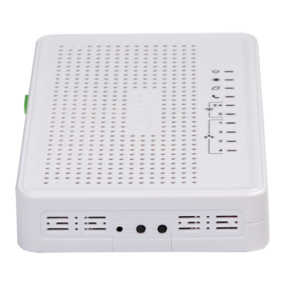
Page 12: Design
Network terminal is a desktop device enclosed in plastic housing. The rear panel of the device is shown in Figure 3. Figure 3 – NTU-RG-1421G-Wac, NTU-RG-1421G-WZ, NTU-RG-1431G-Wac rear panel layout Connectors and controls located on the rear panel of are listed in Table 3. -
Page 13: Ntu-Rg-1421Gc-Wac
____________________________________________________________________________________ Top panel LED indicators are listed in Table 4. Table 4 – Description of Top Panel LEDs Top Panel Element Description power and activity status indicator optical interface activity indicator Internet service status indicator FXS port activity indicator Wi-Fi activity indicator for 2.4GHz Wi-Fi activity indicator for 5GHz 1..4... -
Page 14: Led Indication
CaTV activity indicator Power power indicator LED Indication 2.6.1 NTU-RG-1421G-Wac, NTU-RG-1421G-WZ, NTU-RG-1431G-Wac LED indicators located on the front panel represent the current state of the device. Possible states of the LEDs are listed in Table 8. – Table 8 Light indication of the device... -
Page 15: Ntu-Rg-1421Gс-Wac
____________________________________________________________________________________ flashes packet data transmission is in progress phone is off-hook port is not registered or authorization is not flashes completed on SIP server flashes slowly receiving call signal green Wi-Fi is active 2.4/5 flashes Wi-Fi data transfer Wi-Fi is not active interface with the Internet identifier is not configured interface with the Internet identifier is configured and green... -
Page 16: Indication Of Lan Interfaces
____________________________________________________________________________________ Wi-Fi is not active green phone is off-hook Phone 0 flashes port is not registered or authorization is not completed on SIP server flashes slowly receiving call signal RF port is disabled TV signal is not available signal level does not correspond to the normal (more than orange +2 dBm) The device is disconnected from the power source or... -
Page 17: Architecture Of Devices
____________________________________________________________________________________ ARCHITECTURE OF DEVICES NTU-RG architecture Figure 8 – Logical Architecture of a Device with Factory Settings Main Components of the Device: – optical receiver/transmitter (SFF module) for conversion of an optical signal into electric one – processor (PON chip) which converts Ethernet and GPON interfaces; and Wi-Fi modules for wireless interfaces of the device. - Page 18 ____________________________________________________________________________________ IPInterface block is a logical entity that the IP address is provided for the access in LAN and DHCP server distributing addresses to clients. The ppp0.1 block is WAN interface of the router. In the factory default configuration, this interface is a default interface for such services as the Internet, VoIP, TR-069 device management and IPTV.
-
Page 19: Configuration Of Ntu-Rg-1421G-Wac, Ntu-Rg-1421G-Wz, Ntu-Rg-1431G-W And Ntu-Rg-1421Gc-Wvia Web Interface. User Access
____________________________________________________________________________________ CONFIGURATION OF NTU-RG-1421G-WAC, NTU-RG-1421G-WZ, NTU-RG-1431G-W AND NTU-RG-1421GC-W VIA WEB INTERFACE. USER ACCESS In order to configure the device it's necessary to connect to it in web browser (hypertext document viewer), such as Firefox or Google Chrome. To do this, enter the device IP address in the browser address bar (factory default IP: 192.168.1.1, subnet mask: 255.255.255.0). -
Page 20: The "Device Info" Menu
____________________________________________________________________________________ 4.1 The “Device Info” menu 4.1.1 The “Summary” submenu Board type—device model; – – Serial number—device serial number; PON serial—device serial number in PON network; – Base WAN MAC—MAC address of the device WAN; – – Board ID; Hardware Version—hardware version number; –... -
Page 21: The "Detail" Submenu. Detailed Information
____________________________________________________________________________________ 4.1.2.2 The “Detail” submenu. Detailed Information The tab contains detailed information about existing configurations of the WAN interface. The following information about services can be displayed: – WAN service x – service name; – Interface – interface name; – Type – interface operation mode; –... -
Page 22: The "Route" Submenu. Routing Table Preview
____________________________________________________________________________________ WAN Service: Optical interface: If a device supports measurement of optical signal parameters , the menu displays an additional table: Link status—optical link status; Optical power level—level of the received signal (1490nm); Optical power level of transmitter—level of the transmitted signal (1310nm); ... -
Page 23: The "Arp" Submenu. Display Of The Arp Protocol Cache
____________________________________________________________________________________ Destination—destination IP address; Gateway—gateway IP address; Subnet Mask—subnet mask (Genmask); Flag—routing flag: – U—active route; – ! —inactive route, packets will be rejected; – G—the route uses gateway; – H—destination address is a separate host; –... -
Page 24: The "Wireless Stations" Submenu. Connected Wireless Devices
____________________________________________________________________________________ 4.1.8 The “Wireless Stations” submenu. Connected wireless devices The menu shows a list of authenticated wireless devices and their statuses. The device information is shown in a table with the following parameters: MAC – device MAC address; Associated – SSID association status; ... -
Page 25: The "Voice" Submenu. Monitoring Of Telephone Ports
____________________________________________________________________________________ RSSI—strength of AP signal received by ONT. Click the Refresh button to refresh the information. 4.1.10 The “Voice” submenu. Monitoring of telephone ports The menu shows the status of FXS port and parameters of SIP account. – Status—the status of voice daemon; –... -
Page 26: The "Nat" Submenu. Nat Settings
____________________________________________________________________________________ Static IP Lease List The DHCP Static IP Lease tab is used to establish correspondence between leased IP addresses and devices' МАС addresses (mapping). To add a record into a table, click Add. You can establish up to 32 matches. IP Address—... -
Page 27: The "Port Triggering" Submenu. Port Triggering Settings
____________________________________________________________________________________ – Utilized interface. Only interfaces that are fit for operation in router mode with enabled network address translation will be available. – Service name—service settings: – Select service—select a preconfigured rule; – Custom Service—create new rules not listed in the Select a service list; –... - Page 28 ____________________________________________________________________________________ – Utilized interface. Only interfaces that are fit for operation in router mode with enabled network address translation will be available. – Application name—application settings: – Select application—select a preconfigured rule; – Custom an application—create new rules not listed in the Select an application list. As opposed to the Virtual Server function, PC's IP address should not be fixed in LAN.
-
Page 29: The "Dmz Host" Submenu. Demilitarized Zone Settings
____________________________________________________________________________________ 4.2.2.3 The “DMZ Host” submenu. Demilitarized Zone Settings When an IP address is set in the DMZ host IP address field, all requests from external network that do not satisfy the Virtual Servers rules will be redirected to a DMZ host (a trusted host with the specified address in the local network). - Page 30 ____________________________________________________________________________________ – Filter Name—filter text description; – IP protocol version—IP protocol version; – Protocol—selected protocol (TCP/UDP, TCP, UDP, ICMP); – MAC address—source MAC address; – Source IP address[/prefix length]—source IP address (prefix length can be specified after slash); – Source port (port or port:port)—source port or a range of ports separated by a colon; –...
-
Page 31: The "Mac Filtering Setup" Submenu. Filtering Settings For Mac Addresses
____________________________________________________________________________________ – Filter Name—filter text description; – IP Version—IP protocol version; – Protocol—the network protocol selected; – Source MAC address—source MAC address; – Source IP address[/prefix length]—source IP address (prefix length can be specified after slash); – Source Port (port or port:port)—source port or port range can be specified after double point; –... -
Page 32: The "Parental Control" Submenu: Restriction Settings
____________________________________________________________________________________ МАС filtration can be applied only to interfaces in the bridge mode. In order to change the global policy, set a flag in front of a corresponding interface and click the Change Policy button. Two options are available: FORWARDED and BLOCKED. The created rules will block traffic with specified source/destination MAC addresses in the FORWARDED mode and allow it to pass in the BLOCKED mode. -
Page 33: The "Url Filter" Submenu. Internet Access Restriction Settings
____________________________________________________________________________________ – Username—user name; – Browser’s MAC Address—automatically identified MAC address of the computer for which the schedule is created; – Another MAC Addresses (xx:xx:xx:xx:xx:xx)—manually set MAC address of the computer for which the schedule is created; – Days of the week—days when Internet access is blocked; –... -
Page 34: The "Dynamic Dns" Submenu. Dynamic Dns Configuration
____________________________________________________________________________________ In order to add a new URL to a list, select the checkbox next to the corresponding list (URL List Type) and click the Add button. – URL—URL address; – Port Number—port number (if the field is empty, port 80 will be used). Click the Apply/Save button to add settings to the table. - Page 35 ____________________________________________________________________________________ D-DNS provider—type of D-DNS service (provider): DynDNS.org, TZO.com, ZoneEdit.com, – freedns.afraid.org, easyDNS.com, 3322.org, DynSIP.org, No-IP.com, dnsomatic.com, sitelutions.com; – Custom—another provider chosen by user. In this case user will need to specify the provider's name and address: – User name—user name for the DDNS account; Password—password for the DDNS account;...
- Page 36 ____________________________________________________________________________________ – User name—user name for the DDNS account; Password—password for the DDNS account; – – DynDNS Type—type of the service you registered at your provider: – Dynamic—Dynamic DNS service is registered; Static—Static DNS service is registered; – – Custom—Custom DNS service is registered. –...
-
Page 37: The "Print Server" Submenu. Print Server Configuration
____________________________________________________________________________________ 4.2.6 The “Print Server” submenu. Print Server Configuration Print server is a software or hardware solution that allows users of wired or wireless networks to share a printer at home or at the office. This printer is completely independent from network computers and significantly reduces the burden on user's working environment. -
Page 38: The "Z-Wave" Menu
____________________________________________________________________________________ 4.2.8 The “Z-Wave” menu Use this menu to configure “Smart Home” parameters. – Enable Zway—enable/disable “Smart Home” controller; – Host name—specify IP address of “Smart Home” remote platform; – Port—specify the platform port to which “Smart Home” controller is connected; –... -
Page 39: The "Wireless" Menu. Wireless Network Configuration
____________________________________________________________________________________ The “Wireless” menu. Wireless network configuration This section contains individual settings for each of the operating bands—2.4GHz and 5GHz. 4.3.1 The “Basic” submenu. General settings This menu is intended for general setup of the LAN wireless interface and allows user to specify up to three wireless access points. -
Page 40: The "Security" Submenu. Security Settings
____________________________________________________________________________________ BSSID—МАС address of the access point; – – Country—specifies location (country); – Country RegRev—specifies region ID (0-34 for Russia); Max Clients—the maximum possible number of simultaneously supported wireless connections. – Click the Apply/Save to accept the changes. 4.3.2 The “Security” submenu. Security settings Use this menu to configure general data encryption settings for a wireless network. - Page 41 ____________________________________________________________________________________ Set WPS AP mode—sets WPS mode of the access point. – Shortcomings of WPS Wi-Fi routers supporting the WPS technology have a security vulnerability. This vulnerability allows attackers to retrieve passwords for WPA and WPA2 encryption protocols. The technology is vulnerable as it allows to brute-force the 8-digit network key (PIN).
- Page 42 ____________________________________________________________________________________ TKIP—the encryption protocol used for WPA It implements a more – efficient mechanism of key change management in comparison with WEP; – AES—128-bit block encryption algorithm with 128/192/256-bit key, generally used for WPA2). – Mixed WPA2/WPA—includes a combination of WPA2/WPA (this encryption mode uses WPA2 and WPA protocols, requires the utilization of a RADIUS authentication server);...
-
Page 43: The "Mac Filtering" Submenu. Filtering Settings Of Mac Addresses
____________________________________________________________________________________ RAIUS server (for authentication of wireless clients). – WEP Encryption—select Enable in the drop down list to enable WEP encryption; Encryption—64- or 128-bit key encryption; – – Current Network Key—the key that will be used for connection; – Network Key 1..4—allows specification of 4 different keys, which comprise of 10 hex characters of 5 ASCII characters for 64-bit encryption. -
Page 44: The "Wireless Bridge" Submenu. Wireless Connection Settings In Bridge Mode
____________________________________________________________________________________ 4.3.4 The “Wireless Bridge” submenu. Wireless Connection Settings in Bridge Mode Use this menu to specify access point operation mode: either access point or wireless bridge. When the bridge mode is used, MAC addresses of remote bridges should be specified. This mode is used to establish a wireless connection between two individual networks. -
Page 45: The "Advanced" Submenu
____________________________________________________________________________________ 4.3.5 The “Advanced” submenu Use this menu to configure advanced settings of the wireless network. – Band—set the frequency band (2.4/5GHz); Channel—active channel of the router. Changing operating channel can eliminate interference or – problems that occur in wireless network operation. It is recommended to set this value to ‘Auto’ to avoid the interference caused by the neighbouring networks. - Page 46 ____________________________________________________________________________________ Full—automatic selection mechanism scans and selects a channel from the list of available – channels. – Legacy—automatic selection mechanism scans and selects a channel from the list of channels supported by legacy devices (only for 2.4GHz band). – Custom—automatic selection mechanism scans and selects a channel from the list of channels defined by the user in Allowed Channel settings.
-
Page 47: The "Connection Wizard" Submenu
____________________________________________________________________________________ 4.3.6 The “Connection wizard” submenu Use this menu to configure wireless LAN interface. You can enable or disable the wireless LAN interface, configure the wireless network name (SSID) and set a password (line of 8-63 ASCI characters). Click the Apply/Save button to accept and save the changes. 4.4 The “Storage Service”... -
Page 48: The "Management" Menu. Device Management
____________________________________________________________________________________ — User name – login used to access the network resource; — Password – password used to access the network resource; Confirm password – password confirmation; — — Volume name – path to network resource (the name of the connected storage device is shown on the Storage Device Info page). -
Page 49: The "Pon Password" Submenu. Change The Pon Access Password
____________________________________________________________________________________ 4.5.2 The “PON Password” submenu. Change the PON access password Use this menu to change the password for ONT authorization on the PON station device. To change the password, enter 10 characters into the New PON Password field. Click the Apply/Save button to accept and save the changes. -
Page 50: The "Ping" Submenu. Test The Availability Of Network Devices
____________________________________________________________________________________ 4.5.4 The “Ping” submenu. Test the Availability of Network Devices Use this menu to test the availability of network devices connected to the router with Ping utility. In order to check availability of a connected device, enter its IP address into the field and click the Ping button. -
Page 51: The "System Log" Submenu. System Log Review And Configuration
____________________________________________________________________________________ 4.5.6 The “System Log” submenu. System Log Review and Configuration 4.5.6.1 The “Configuration” submenu. System Log Configuration Use the menu to configure events occurring on the router. – System log – enable/disable system log; – Log level – verbosity of the event log. Severity levels in the descending order: –... -
Page 52: The "View" Submenu. System Log Display
____________________________________________________________________________________ 4.5.6.2 The “View” submenu. System Log Display The menu is used to configure display of router's events. Use the Refresh button to refresh the information. 4.5.7 The “Update Software” submenu In order to update software, select the software in the Software File name field (use the Choose File button) and click Update Software. -
Page 53: Ntu-Rg Acceptance Certificate And Warranty
Equipment shipping and storage should be conducted in accordance with GOST 15150 Conditions 5 and Conditions 1 respectively. The manufacturer, Eltex Enterprise Ltd., guarantees that optical network gateway complies with technical specifications RPTL.465600.108TU under operational conditions described in this manual, which should be maintained by the user.
Need help?
Do you have a question about the NTU-RG-1421G-WZ and is the answer not in the manual?
Questions and answers