
Subscribe to Our Youtube Channel
Related Manuals for ELTEX NTU-52V


Summary of Contents for ELTEX NTU-52V
- Page 1 Optical network terminals User manual Firmware version 1.2.1 IP address: 192.168.1.1 Username: user Password: user...
-
Page 2: Table Of Contents
NTU-52V/VC. User manual (user) Contents Introduction ............................4 Product Description ..........................5 Purpose ..............................5 Models ..............................5 Device Specification ..........................6 Key Specifications ..........................8 Design ..............................11 Light Indication ............................13 Delivery Package..........................17 NTU-52V/VC architecture........................18 Device configuration via Web interface. Administrator Access ............19 The 'Status' menu. Device Information....................21 5.1.1 The 'Device status' submenu. - Page 3 NTU-52V/VC. User manual (user) The 'Admin' menu ..........................42 5.6.1 The 'Settings' submenu. Configuration restore and reset..............42 5.6.2 The 'Commit/Reboot' submenu. Saving changes and rebooting the device ........42 5.6.3 The 'Logout' submenu .........................43 5.6.4 The 'Password' submenu. Access control configuration (setting passwords) .......43 5.6.5 The 'Firmware upgrade' submenu.
-
Page 4: Introduction
ONT device is designed to connect user terminal equipment to broadband access services. It can be used in residential areas and office buildings. The range of ONT NTU equipment produced by ELTEX comprises of terminals with two UNI interfaces of ... -
Page 5: Product Description
2 Product Description 2.1 Purpose NTU-52V/VC GPON ONT (Gigabit Ethernet Passive Optical Network) devices represent high-performance user terminals designed to establish a connection with upstream passive optical network equipment and to provide broadband access services to the end user. GPON connection is established through the PON interface, while Ethernet interfaces are used for connection of terminal equipment. -
Page 6: Device Specification
NTU-52V/VC. User manual (user) 2.3 Device Specification Device is equipped with the following interfaces: • Ports to connect network devices (FXS): • 1 RJ-11 port • 1 RJ-45 port • 1xPON SC/APC port for connection to provider's network (WAN);... - Page 7 NTU-52V/VC. User manual (user) • Remote monitoring, configuration and setup: • TR-069; • Web interface; • OMCI. • CaTV Only for NTU-52VC The figures below illustrate applications schemes of NTU-52V/VC. Figure 1 – NTU-52V and NTU-52VC application diagram...
-
Page 8: Key Specifications
NTU-52V/VC. User manual (user) 2.4 Key Specifications Table 2 shows main specifications of the terminals: Table 2 — Main Specifications VoIP protocols Supported protocols Audiocodecs G.729, annex A Codecs G.711(A/µ) G.723.1 (5,3 Kbps) Fax transmission: G.711, T.38 Ethernet LAN interface parameters... - Page 9 NTU-52V/VC. User manual (user) 20 km Maximum range of coverage 1310 nm Transmitter: 1244 Mbps • Upstream connection speed +0,5 to +5 dBm • Transmitter power 1 nm • Optical spectrum width (RMS) 1490 nm Receiver: 2488 Mbps •...
- Page 10 NTU-52V/VC. User manual (user) General parameters NTU-52V NTU-52VC Model 12 VDC/220 VAC power adapter 12 VDC/220 VAC power adapter Power supply RF port 10 W Max. power consumption From +5 to +40°С Operating temperature 80% max. Relative humidity 147×110×24 mm 160×120×40 mm...
-
Page 11: Design
Subscriber terminal is designed as desktop device in plastic housing. The rear panel layout of the devices is depicted in Fig. 2, 3. Figure 2 — NTU-52V rear panel layout Connectors and controls located on the rear panel of 52V are listed in Table Table 3 –... - Page 12 Phone RJ-11 connector for analogue phone connection SC port (socket) for PON with GPON interface The side panel layout of the NTU-52V is depicted in figure below. Figure 4 — NTU-52V side panel layout Table 5 for detailed information about buttons located on the side panel of the device.
-
Page 13: Light Indication
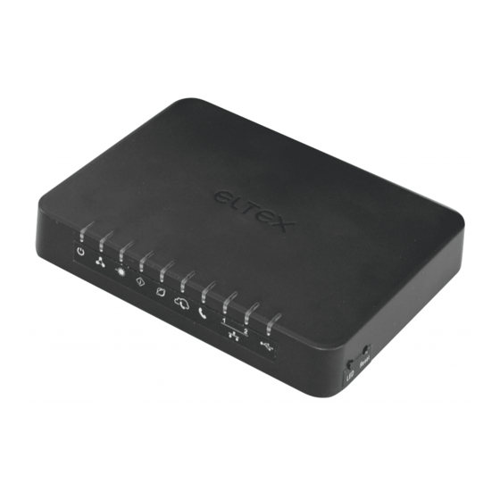
NTU-52V/VC. User manual (user) 3.1 Light Indication The top panel layout of the NTU-52V is depicted in Fig. 5, the front panel layout is depicted in Fig. Figure 5 — NTU-52V top panel layout Figure 6 — NTU-52V front panel layout The LED indicators located on the top and front panels show the current device status. - Page 14 NTU-52V/VC. User manual (user) Table 6 – Description of NTU-52V front and top panel LEDs Front panel element LED Status Description green power is connected - power indicator power is not connected flashes slowly the firmware update process is in - operation status indicator...
- Page 15 NTU-52V/VC. User manual (user) Front panel element LED Status Description green phone is on hook green established 10/100 Mbps connection - 1..2 – Ethernet port activity indicator orange established 1000 Mbps connection flashes green/orange data transfer is in progress rapidly USB device is not connected - USB port operation indicator...
- Page 16 NTU-52V/VC. User manual (user) Table 7 – Description of NTU-52VC front panel LEDs Front panel element LED Status Description phone is off hook – FXS port activity indicator flashes green receiving a call green phone is on hook green established 10/100 Mbps -1 – 10/100 Mbps Ethernet port...
-
Page 17: Delivery Package
'Reset' button and hold it for 7-10 seconds until the indicator glows red and all other LEDs go out. Factory settings for IP address are: LAN - 192.168.1.1, subnet mask – 255.255.255.0. Access can be provided from LAN 1 and LAN 2. 3.2 Delivery Package The NTU-52V/VC standard delivery package includes: • NTU-52V/VC optical network terminal; •... -
Page 18: Ntu-52V/Vc Architecture
NTU-52V/VC. User manual (user) 4 NTU-52V/VC architecture Figure 8 – Logical architecture of a device with factory settings Main Components of the Device: • Optical receiver/transmitter (SFF module) for conversion of an optical signal into an electric one;... -
Page 19: Device Configuration Via Web Interface. Administrator Access
NTU-52V/VC. User manual (user) 5 Device configuration via Web interface. Administrator Access Getting Started To configure the device, it is necessary to connect to it through Web browser: 1. Open the Web browser (program for viewing hypertext documents), for example, Firefox, Google Chrome and etc. - Page 20 NTU-52V/VC. User manual (user) Main elements of the web interface General view of the device configuration window is depicted below. The user interface window can be divided into 3 parts: The navigation tree on the device settings menu. The main settings window for the selected section.
-
Page 21: The 'Status' Menu. Device Information
NTU-52V/VC. User manual (user) 5.1 The 'Status' menu. Device Information 5.1.1 The 'Device status' submenu. Device General Information This section displays general information about the device, the main parameters of the LAN and WAN interfaces. Status → Device status System •... -
Page 22: The 'Ipv6 Status' Submenu. Information About Ipv6 System
NTU-52V/VC. User manual (user) LAN Configuration • IP Address – device IP address; • Subnet Mask – device subnet mask; • DHCP Server – DHCP server state; • MAC Address – device MAC address. WAN Configuration • Interface – interface name;... -
Page 23: The 'Pon' Submenu. Optical Module Status Information
NTU-52V/VC. User manual (user) 5.1.3 The 'PON' submenu. Optical module status information The tab displays the current status of PON interface system. Status → PON PON Status • Vendor Name – manufacturer name; • Part Number – part number; • Temperature – current temperature;... -
Page 24: The 'Lan' Menu Lan Interface Configuration
NTU-52V/VC. User manual (user) 5.2 The 'LAN' menu LAN interface configuration You can configure main parameters of LAN interfaces in this section. • Interface name – interface name; • IP Address – interface IP address; • Subnet Mask – interface subnet mask;... -
Page 25: The Services Menu. Service Configuration
NTU-52V/VC. User manual (user) 5.3 The Services menu. Service configuration 5.3.1 The 'DHCP Setting' submenu. DHCP configuration The menu allows DHCP server and DHCP repeater configuration. Services → DHCP (Server) • DHCP Mode– select operation mode: • NONE – DHCP disabled;... -
Page 26: The 'Dynamic Dns' Submenu. Dynamic Dns Configuration
Dynamic DNS (domain name system) allows information to be updated on DNS server in real time and (optionally) automatically. It is applied for assignment of a constant domain name to a device (computer, router, e.g. NTU-52V/VC) having a dynamic IP address. The IP address can be assigned by IPCP in PPP connections or in DHCP. ... -
Page 27: The 'Firewall' Submenu. Firewall Configuration
NTU-52V/VC. User manual (user) DynDns/No-IP Settings: • UserName – user name; • Password – authorization password on the service selected for operation with D-DNS. 'Dynamic DNS Table' table with the list of available DNS displayed in this section. To add a record, click the 'Add' button. - Page 28 NTU-52V/VC. User manual (user) Added filters are displayed in the 'Current Filter Table' located below. The entries in this table are used to restrict certain types of data packets pass through the gateway. To delete a specific filter, select the position and click the 'Delete selected' button, to delete all filters click 'Delete All'.
- Page 29 NTU-52V/VC. User manual (user) 5.3.3.3 The 'Port Forwarding' submenu. Port forwarding configuration 'Current Port Forwarding Table' with port forwarding information is displayed in this section. Entries in this table allow you to automatically redirect common network services to a specific machine behind the NAT firewall.
- Page 30 NTU-52V/VC. User manual (user) URL or keyword from the table, click on it and then on the 'Delete Selected' button. To delete all restrictions click the 'Delete All' button. Services → Firewall → URL Blocking • URL Blocking (Enable/Disable) – enable/disable URL Blocking operation;...
- Page 31 NTU-52V/VC. User manual (user) 5.3.3.6 The 'Port Triggering' submenu. Dynamic port opening configuration Not supported in the current firmware version 1.2.1 When a certain event occurs, ports on its external interface are dynamically opened, which are tied to the corresponding ports on the computer on the local network.
-
Page 32: The 'Upnp' Submenu. Automated Setup Of Network Devices
NTU-52V/VC. User manual (user) 5.3.4 The 'UPnP' submenu. Automated Setup of Network Devices In this section you can configure Universal Plug and Play (UPnP™) function. UPnP ensures compatibility with network equipment, software and peripheral devices. Services → UPnP The use of UPnP requires NAT setup on an active WAN interface. -
Page 33: The 'Samba' Submenu. Configuration Of Samba Users
NTU-52V/VC. User manual (user) Interfaces with the support for RIP are displayed in the 'RIP Config Table'. To delete all entries in the table click the 'Delete All' button; to delete one position from the list select it and click 'Delete Selected'. -
Page 34: The 'Advance' Menu. Advanced Settings
NTU-52V/VC. User manual (user) • Path – path to library; • Read only – read only; • Write list – list of accounts who can change files in the library; • Comment – comment for the library. 5.4 The 'Advance' menu. Advanced settings 5.4.1 The 'ARP Table' menu. -
Page 35: The 'Routing' Submenu. Routing Configuration
NTU-52V/VC. User manual (user) To view the information about bridge and its connected ports click the 'Show MACs' button. Advance → Bridging → Show MACs • Port – port number; • MAC Address – MAC address; • Is Local – local address;... -
Page 36: The 'Bridging Grouping' Submenu. Interface Grouping
NTU-52V/VC. User manual (user) To view the routes that the device often accesses, click the 'Show Routes' button, then the 'IP Route Table' will be displayed. Advance → Routing → Show Routes To update the information in the table, click the 'Refresh' button, to close the table, click 'Close'. -
Page 37: The 'Link Mode' Submenu. Lan Ports Configuration
NTU-52V/VC. User manual (user) 5.4.5 The 'Link mode' submenu. LAN ports configuration In this submenu you can set the LAN ports operation mode. LAN1/2 – operation mode configuration; available modes: 10M Half Mode, 10M Full Mode, 100M Half Mode, 100M Full Mode and Auto Mode (auto-negotiation mode). - Page 38 NTU-52V/VC. User manual (user) • AdvManagedFlag – enable/disable 'Managed' flag sending in RA; • AdvOtherFlag – enable/disable Other RA flag sending. To save the changes, click the 'Apply Changes' button. 5.4.6.2 The 'DHCPv6 setting' submenu. DHCPv6 server configuration This submenu is used to configure DHCPv6 server. By default, it operates in auto configuration mode (DHCPServer(Auto)) via prefix delegation.
- Page 39 NTU-52V/VC. User manual (user) 5.4.6.4 The 'MLD snooping' submenu. MLD snooping function configuration In this section you can enable/disable MLD-snooping operation. For this you should check 'Enable/Disable'. Advance → IPv6 → MLD snooping To save the changes, click the 'Apply Changes' button.
- Page 40 NTU-52V/VC. User manual (user) Advance → IPv6 → IPv6 routing → Show Routes • Destination – destination network; • Next Hop – nest host • Flags – flags; • Metric – metric; • Ref – route source; • Use – route usage;...
-
Page 41: The 'Diagnostics' Menu
NTU-52V/VC. User manual (user) • Allow – when checked, traffic pass is allowed by default; • Protocol – select protocol; • Source Interface ID – source interface; • Destination Interface ID – destination interface; • Source Port – source port; • Destination Port – destination port. -
Page 42: The 'Admin' Menu
NTU-52V/VC. User manual (user) 5.6 The 'Admin' menu Device management section. In this menu, you can configure passwords, time, configurations, etc. 5.6.1 The 'Settings' submenu. Configuration restore and reset Admin → Settings → Backup Settings In this section, you can copy the current settings to a file (Backup Settings) by clicking on the 'Backup Settings to File' button. -
Page 43: The 'Logout' Submenu
NTU-52V/VC. User manual (user) 5.6.3 The 'Logout' submenu In this section it is possible to log out by clicking on the 'Logout' button. Admin → Logout 5.6.4 The 'Password' submenu. Access control configuration (setting passwords) In this section you can change a password to access the device. -
Page 44: The 'Firmware Upgrade' Submenu. Software Update
NTU-52V/VC. User manual (user) 5.6.5 The 'Firmware upgrade' submenu. Software Update To update firmware, it is necessary to select firmware file by using the 'Select file' button and click 'Upgrade'. To reset the value, click the 'Reset' button. Admin → Firmware upgrade Do not switch off or reboot the device during the update. The process may take several minutes. The device will be automatically rebooted when the update is completed. -
Page 45: The 'Time Zone' Submenu. System Time Configuration
NTU-52V/VC. User manual (user) • Subnet Mask – subnet mask; • Port – destination port. To add a rule fill the corresponding fields and click the 'Add' button. Added rules are displayed in the 'RA Table'. To activate/deactivate the selected rule, click the 'Toggle selected' button. To delete one rule, select it with a flag in the Select column and click the 'Delete Selected' button. -
Page 46: The 'Statistics' Menu. Traffic Flow Information For Device Ports
NTU-52V/VC. User manual (user) 5.7 The 'Statistics' menu. Traffic flow information for device ports 5.7.1 The 'Interface' submenu. Information about timers and errors This section displays timers/errors for packets for each interface: Statistics → Interface • Interface – interface; •... -
Page 47: Th 'Pon' Submenu
NTU-52V/VC. User manual (user) 5.7.2 Th 'PON' submenu This section displays timers for the optical interface: Statistics → PON • Bytes Sent – transmitted bytes; • Bytes Received – received bytes; • Packets Sent – packets transmitted; • Packets Received – packets received;... -
Page 48: The List Of Changes
NTU-52V/VC. User manual (user) 6 The list of changes Document version Suitable firmware version Issue date Revisions Version 1.0 1.2.1 01.2020 First issue...
Need help?
Do you have a question about the NTU-52V and is the answer not in the manual?
Questions and answers