NAPCO XP-400 Programming Instructions Manual
Dealer program mode - keypad key definition
Hide thumbs
Also See for XP-400:
- Installation instructions manual (28 pages) ,
- Using instruction (16 pages) ,
- Using instructions (16 pages)
Table of Contents
Advertisement
Quick Links
XP-400 Programming Instructions
®
Note: These Programming Instruction are intended to be used in conjunction with WI854C,
please refer to WI854C for additional information, instructions and definitions.
DEALER PROGRAM MODE
Hexadecimal Data Entry
To Enter a hexadecimal digit
enter the following:
A=
A 1
D=
A 4
B=
A 2
E=
A 5
C=
A 3
F=
A 6
Scroll Key
Use this key to scroll
through data that has been
entered in Programming
Blocks.
Entering Dealer Program Mode
N
:
OTE
Entering Dealer Program Mode is not permitted while the panel
is Armed, Reporting, or the Bell Output is on. To Enter Dealer
Mode while the Bell is ON or the panel is Reporting or Armed;
power up the panel and enter Dealer Mode within the first 3
b
minutes. Pressing the
key clears the 3 minute timer.
Exiting Dealer Program Mode
-
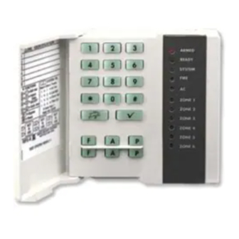
KEYPAD KEY DEFINITION
ARMED
1 2 3
READY
4 5 6
j
j
SYSTEM
FIRE
7 8 9
AC
A 0 B
ZONE 1
ZONE 2
C
D
ZONE 3
ZONE 4
K F G
ZONE 5
ZONE 6
K F G
NAPCO
+
Enter
A 8
Default Dealer Code shown in parentheses
Enter
B A 8
N
:
OTE
After 15 minutes of keypad inactivity the keypad
will emit a steady tone indicating the panel has been
left in Dealer Program Mode. Enter Dealer Code to
exit or press the
Set Key
Press this key before
entering a Program-
ming Block Number.
Blank Key
Press this key to disable all fea-
tures within a LED type Program-
ming Block or to blank out digits in
a Direct Entry type Programming
Block.
Dealer Code
(4) (5) (6) (7)
Dealer Code
(4) (5) (6) (7)
D
EFAULTING THE
1. Remove power from the panel.
2. Remove all wiring from terminal
15 (PGM) and terminal 3.
B
key to return to Dealer
3. Connect terminal 15 (PGM) to
terminal 3.
4. Apply power to the XP-400 con-
trol panel.
5. After a few seconds the ARMED,
READY and
BLE LEDs will flash.
6. The keypad will beep 3 times
indicating the panel default val-
ues have been loaded.
7. Remove wiring between terminal
15 (PGM) and terminal 3.
8. Re-install original wiring for ter-
minal 15 (PGM) and terminal 3.
Note:
Dealer Options 1 [96] and Dealer
Options 2 [97] will not be de-
faulted. If Dealer Code Lockout
has been programmed the panel
will not default the Dealer Code.
ARMED
ON
Indicates the panel is in Dealer
Program Mode. The panel is
READY
OFF
ready for a programming block
number to be entered.
ü
SYSTEM
FLA
HING
S
ARMED
FLASHING
Indicates the panel is
Ready to exit
READY
FLAS
ING
H
Program Mode.
the Dealer Code to exit.
ü
SYSTEM
FLASHING
P
ANEL
j
SYSTEM TROU-
Any
programming
in
Dealer
Enter
WI854C 8/97
Advertisement
Table of Contents

Related Manuals for NAPCO XP-400


Summary of Contents for NAPCO XP-400
- Page 1 WI854C for additional information, instructions and definitions. exit or press the key to return to Dealer 3. Connect terminal 15 (PGM) to terminal 3. 4. Apply power to the XP-400 con- DEALER PROGRAM MODE KEYPAD KEY DEFINITION trol panel. 5. After a few seconds the ARMED,...
- Page 2 Types of Programming Blocks LED Programming Block Enable features by pressing the key that corresponds to the associated feature; the LED will turn ON. To disable a feature press the key again; the LED will turn OFF. To disable all features within a LED Type Programming Block press the key;...
- Page 3 Blocks, data that has ZONE 1 sistance, Contact been entered as a ‘0’ will be displayed as an ‘A’: ZONE 2 the Napco Toll Subscriber ID Numbers, Phone Numbers, Pager Free Helpline ( ZONE 3 Leading and Trailing digits and Report Codes.
-
Page 4: Zone Features
Zone Features Auto Bypass Reentry Zones Exit/Entry Zones Open Circuit Zones Default Default Default Zone 1 Zone 1 Zone 1 See wiring Zone 2 Zone 2 Zone 2 diagram for Zone 3 Zone 3 Zone 3 Open Circuit wiring. Zone 4 Zone 4 Zone 4 Home/Away with Delay Zones... -
Page 5: System Times
System Times System Features Exit Delay Keypad Features 1 Programmable Output (PGM) Features 2 Default Default Exit Delay, seconds Zn 1 LED ON = *Keypad Panic 2 ( Zn 1 LED ON = Reserved Maximum Entry 255 Zn 2 LED ON = *Keypad AUX ( Zn 2 LED ON = AUX Zn 3 LED ON = *Keypad Panic ( Zn 3 LED ON = Panic... -
Page 6: Telephone Number 1 Programming
Telephone Number 1 Programming Subscriber ID Number Zone Report, Telco 1 System Reporting, Telco 1 Default Default Zone 1 Zn 1 LED ON = AC Fail Report (15 min. report delay) Zone 2 Zn 2 LED ON = Low Battery Report Zone 3 Zn 3 LED ON = *Trouble Report Telephone Number 1... -
Page 7: Backup Telephone Programming
Backup Telephone Programming Subscriber ID Number (Telco 2) Dialing Prefix Dialing Prefix for Telco 1, Telco 2 & Telco 3. Telephone Number 2 Communicator Features 1 Default Zn 1 LED ON = Communicator Enabled A fixed Dial Tone Detection (E) is included prior to the Dialing Prefix (Block Zn 2 LED ON = DTMF w/ Rotary Back up Number 44). -
Page 8: Telephone Number 3 Programming
Telephone Number 3 Programming Subscriber ID Number Zone Report, Telco 3 System Reporting, Telco 3 Default Default Zone 1 Zn 1 LED ON = AC Fail Report (15 min. report delay) Zone 2 Zn 2 LED ON = Low Battery Report Zone 3 Zn 3 LED ON = *Trouble Report Telephone Number 3... -
Page 9: Report Codes
Report Codes Zone Report Codes Zone Codes Opening and Closing Code Zone 1 Alarm Code Zone 1, 2, 3 & 4 Restore Code The second digit of the Re- Closing Code port Code is the number of Zone 2 Alarm Code Zone 1, 2, 3 &... - Page 10 Wireless Transmitters RF ID # Point Programming Example Map point 1 of a window door transmitter, with RF ID# 0012B0:0 Zone 1 Enter the RF ID# located on to Zone 3. the Transmitter and Key Fob labels. 73 Zone 3 Zone 2 B 0 :0 Zone 3...
-
Page 11: Dealer Programming
Downloading Dealer Programming Callback Telephone Number Dealer Code Dealer Options 2 Default Zn 1 LED ON = *International Dialing Protocol (4) (5) (6) (7) Zn 2 LED ON = *Invert Bell Output Zn 3 LED ON = System Trouble Auto Reset Ring Count Zn 4 LED ON = User 1 Code-Program only User 1 Code... - Page 12 XP-400 WIRING DIAGRAM (REFER TO INSTALLATION INSTRUCTIONS WI853C) RECHARGEABLE BATTERY 12 VDC 4AH OR 7AH RESIDENTIAL BURG (4 HOUR STANDBY) BLACK COMBINED STANDBY = 350 mA BELL = 2.0 AMP ALL OUTPUTS ARE CURRENT LIMITED COLD WATER GROUND CONNECTION NOT USED...
Need help?
Do you have a question about the XP-400 and is the answer not in the manual?
Questions and answers