Table of Contents
Advertisement
Quick Links
Operator's Manual
Always Wear Eye Protection During Operation
Gasoline containing up to 10% ethanol (E10) is acceptable for use in this machine.
The use of any gasoline exceeding 10% ethanol (E10) will void the product warranty.
115 75 44-27 Rev. 2
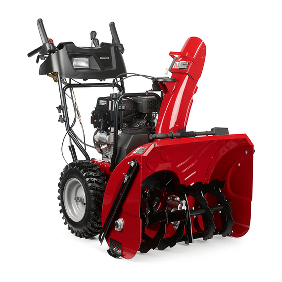
ST 3368P
12.20.17 TH/SR
WARNING:
Read this Man u al and follow all Warnings
and Safety Instructions. Fail ure to do so
can re sult in serious in ju ry.
Printed in U.S.A.
Advertisement
Table of Contents

Related Manuals for Jonsered ST 3368P


Summary of Contents for Jonsered ST 3368P
- Page 1 ST 3368P Operator's Manual WARNING: Read this Man u al and follow all Warnings and Safety Instructions. Fail ure to do so can re sult in serious in ju ry. Always Wear Eye Protection During Operation Gasoline containing up to 10% ethanol (E10) is acceptable for use in this machine.
-
Page 2: Safety Rules
IMPORTANT Safe Operation Practices for Walk-Behind Snow Throwers This snow thrower is capable of amputating hands and feet and throwing objects. Failure to observe the following safety instructions could result in serious injury. WARNING: Snow throwers have ex- Look for this symbol to point out im- posed rotating parts, which can cause por tant safety precautions. -
Page 3: Table Of Contents
Clearing a Clogged Discharge Chute 6. When cleaning, repairing or inspecting the snow thrower, stop the engine and make certain the collector/ Hand contact with the rotating impeller inside the discharge impeller and all moving parts have stopped. Disconnect chute is the most common cause of injury associated with the spark plug wire and keep the wire away from the snow throwers. - Page 4 PARTS PACKED SEPARATELY IN CARTON (1) RETAINER SPRINGS (1) MULTI- SAFTEY (1) WASHER 3/8 (1) LOCKNUT 3/8 WRENCH IGNITION KEY (S) (6) LOCKNUTS (6) SHEAR BOLTS 1/4-20 x 1-3/4 1/4-20 (2) FLAT WASHERS UHMW SKID PLATES (2) CARRIAGE BOLTS (1) SPRING (1) LOCKNUT (1) CARRIAGE BOLT 3/8-16 x 2.25...
-
Page 5: Assembly / Pre-Operation
ASSEMBLY / PRE-OPERATION Read these instructions and this manual in its entirety INSTALL SPEED CONTROL ROD (See Figs. 1 and 2) before you attempt to assemble or operate your new 1. Remove plastic tie securing rod to lower handle. snow thrower. Reading the entire manual will familiar- 2. - Page 6 ASSEMBLY / PRE-OPERATION INSTALL TRACTION DRIVE CONTROL ROD INSTALL AUGER CONTROL ROD (See Figs. 5 and 6) (See Figs. 3 and 4) The auger control rod is installed on the snow thrower. The traction drive control rod is installed on the snow thrower. 1.
- Page 7 ASSEMBLY / PRE-OPERATION INSTALL DISCHARGE CHUTE / CHUTE ROTATOR INSTALL CHUTE DEFLECTOR REMOTE CONTROL HEAD (See Fig. 7) (See Figs. 8 and 9) 1. Install remote cable bracket to discharge chute with NOTE: The multi-wrench provided in your parts bag may 5/16-18 carriage bolt and 5/16-18 locknut as shown.
-
Page 8: Operation
OPERATION KNOW YOUR SNOW THROWER READ THIS OWNER'S MANUAL AND ALL SAFETY RULES BEFORE OPERATING YOUR SNOW THROWER. Compare the illustrations with your snow thrower to familiarize yourself with the location of various controls and adjustments. Save this manual for future reference. These symbols may appear on your snow thrower or in literature supplied with the product. - Page 9 OPERATION AUGER DRIVE SPEED MUF FLER CONTROL CON TROL LEVER DEFLECTOR POWER CORD LEVER CHOKE CON TROL REMOTE GAS O LINE PLUG CONTROL LEVER FILLER CAP THROTTLE DISCHARGE CON TROL ELECTRIC CHUTE START ON/OFF CONTROL BUTTON SWITCH LEVER LIGHT TOOLBOX PRIM ER LH TURN TRIGGER...
- Page 10 OPERATION The operation of any snow thrower can result TO USE THROTTLE CONTROL (See Fig. 13) in foreign objects thrown into the eyes, which The throttle control is located on the engine. Always op er ate can result in severe eye damage. Always wear the snow thrower with the engine at full throttle.
- Page 11 OPERATION TO MOVE FORWARD AND BACKWARD (See Fig. 17) TO THROW SNOW (See Fig. 15) SELF-PROPELLING, forward and reverse movement of The auger rotation is controlled by the auger control lever the snow thrower, is controlled by the traction drive control located on the right side handle.
- Page 12 OPERATION POWER STEERING OPERATION (See Fig. 18) SCRAPER BAR (See Fig. 19) Steering triggers are used to assist in steering your snow After con sid er able use it may become worn. Replace a thrower. The triggers are located on the underside of each dam aged or worn scrap er bar.
- Page 13 OPERATION COLD START - ELECTRIC STARTER CAUTION: Alcohol blended fuels (called gas o- 1. Insert safety ignition key (tied to recoil start cord) into hol or using ethanol or methanol) can attract moisture which leads to separation and for ma- ignition slot until it clicks.
- Page 14 OPERATION IF RECOIL STARTER HAS FROZEN If the recoil starter has frozen and will not turn the engine, proceed as follows: 1. Grasp the recoil starter handle and slowly pull as much rope out of the starter as possible. 2. Release the recoil starter handle and let it snap back against the starter.
-
Page 15: Maintenance Schedule
MAINTENANCE GENERAL REC OM MEN DA TIONS LUBRICATION CHART ➀ The warranty on this snow thrower does not cover items SAE 30 Motor Oil that have been sub ject ed to operator abuse or negligence. ➁ See “ENGINE” in To receive full value from the warranty, operator must Maintenance section maintain snow thrower as in struct ed in this manual. - Page 16 MAINTENANCE BELTS TO CHANGE ENGINE OIL Check belts for deterioration and wear after every 50 hours Determine temperature range anticipated before next oil of operation and replace if necessary. The belts are not change. All oil must meet API service classification SG–SL. ad just able.
-
Page 17: Service And Adjustments
SERVICE AND ADJUSTMENTS IMPELLER SHEAR BOLTS WARNING: To avoid serious injury, before The impeller is secured to the impeller shaft with two (2) performing any service or ad just ments: capscrew/shear bolts and hex nuts. Should a foreign object 1. Be sure the on/off switch is in the or ice become lodged in the impeller, the capscrews are OFF position. - Page 18 SERVICE AND ADJUSTMENTS TO REPLACE BELTS (See Fig. 24) HINT: Insert a 3/8" drive ratchet (in the “ON” position) into the square hole in idler arm and rotate ratchet clockwise The auger and traction drive belts are not adjustable. If the to relieve tension.
- Page 19 SERVICE AND ADJUSTMENTS TO ADJUST CABLE TENSION (See Fig. 26) TO REMOVE WHEELS (See Fig. 25) Adjust cable tension by turning the adjuster turn buckle, • Remove the wheel pin and retainer pin and remove located on the right hand cable. Grasp the long section wheel from axle.
-
Page 20: Storage
STORAGE ENGINE OIL Immediately prepare your snow thrower for storage at the end of the season or if the unit will not be used for 30 Drain oil (with engine warm) and replace with clean engine days or more. oil. (See “ENGINE” in the Maintenance section of this man ual). -
Page 21: Troubleshooting
TROUBLESHOOTING See appropriate section in manual unless directed to a service center/department. PROBLEM CAUSE CORRECTION Does not start 1. Fuel shut-off valve (if so equipped) 1. Turn fuel shut-off valve to OPEN position. in OFF position. 2. Safety ignition key is not inserted. 2. - Page 22 SERVICE NOTES...
- Page 23 SERVICE NOTES...
- Page 24 1-800-487-5951 (U.S.) 1-800-805-5523 (Canada) 8:00 AM to 7:00 PM EST...
Need help?
Do you have a question about the ST 3368P and is the answer not in the manual?
Questions and answers