Advertisement
Quick Links
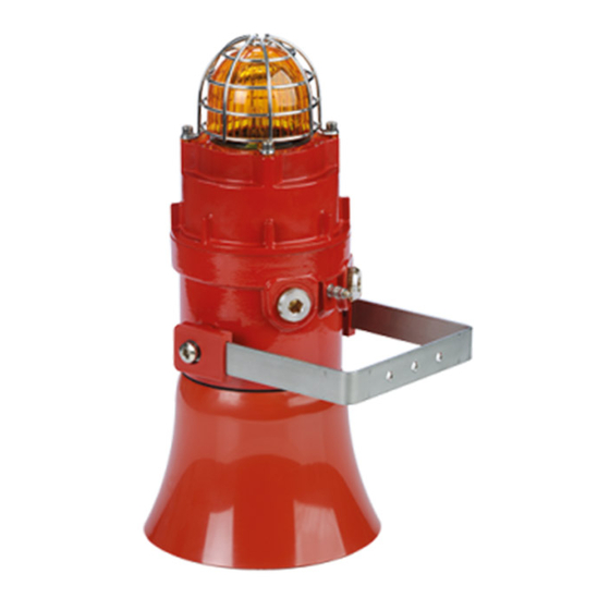
INSTRUCTION MANUAL
STExC1
Combined Sounder & Beacon
For use in Flammable Gas and Dust Atmospheres
1) Product Table
Standards
ATEX / IECEx &
UKEx only
ATEX / IECEx / UKEx
/ NEC / CEC
ATEX / IECEx &
UKEx only
ATEX / IECEx / UKEx
/ NEC / CEC
ATEX / IECEx &
UKEx only
ATEX / IECEx / UKEx
/ NEC / CEC
ATEX / IECEx &
UKEx only
ATEX / IECEx / UKEx
/ NEC / CEC
*Max = Tone 4
†
Nom. = Tone 44
‡
x ̄ = Average over 64 tones
The table shows the input current taken by the various sounders.
The current levels shown above are for the 440Hz Continuous tone @ nominal input voltage.
Nominal current at nominal voltage and 1Hz flash rate.
Max rated current at worst case supply voltage.
Table 1 – Electrical Ratings.
Ensure the system power supply is capable of providing the maximum current required for all beacons. Review associated cable size,
length and quantity of beacons on each circuit.
E2S Warning Signals
Impress House, Mansell Road, Acton, London W3 7QH
Document No. D199-00-601-IS
STExC1X05R
Unit Type Code
Input Voltage
STExC1X05RDC012
STExC1X05RDC024
STExC1X05RDC048
STExC1X05RAC230
STExC1X05FDC012
STExC1X05FDC024
STExC1X05FDC048
STExC1X05FAC230
Issue 6
Nominal
Nominal
Input
Current
12Vdc
885mA
24Vdc
508mA
48Vdc
325mA
230Vac
127mA
12Vdc
885mA
24Vdc
508mA
48Vdc
325mA
230Vac
127mA
13-05-22
STExC1X05F
Voltage
Max.
Range
Current
11.5-14Vdc
1,002mA
20-28Vdc
555mA
42-54Vdc
427mA
220-240Vac
149mA
50/60Hz
11.5-14Vdc
1,002mA
20-28Vdc
555mA
42-54Vdc
427mA
220-240Vac
149mA
50/60Hz
www.e2s.com
Sound
Pressure Level
dB(A)
.†
Max*
Nom
109
101
109
101
115
109
115
109
Tel: +44 (0)208 743 8880
Sheet 1 of 9
Advertisement

Related Manuals for E2S STExC1


Summary of Contents for E2S STExC1
- Page 1 Ensure the system power supply is capable of providing the maximum current required for all beacons. Review associated cable size, length and quantity of beacons on each circuit. E2S Warning Signals Impress House, Mansell Road, Acton, London W3 7QH www.e2s.com Tel: +44 (0)208 743 8880 Document No.
- Page 2 Explosive Atmospheres - Part 1: Equipment Protection by important information. Flameproof Enclosures 'd' Ratings Products may have further approvals, see E2S website for further details. STExC1X05: Class 1 Zone 1 AEx db IIC T5 Gb Ta. -50° to +50°C DC024 Class 1 Zone 1 AEx db IIC T4 Gb Ta.
- Page 3 AC 117 ºC Figure 2: Fixing Location for STEx Combined Beacon and Alarm Equipment Category Horn Sounder. 2G / 2D E2S Warning Signals Impress House, Mansell Road, Acton, London W3 7QH www.e2s.com Tel: +44 (0)208 743 8880 Document No. D199-00-601-IS...
-
Page 4: Installation Requirements
Figure 4: Access to the Sounder PCB Terminals. issues of the relevant standards. The thumbscrews must be re-tightened after rotating the beacon board in. E2S Warning Signals Impress House, Mansell Road, Acton, London W3 7QH www.e2s.com Tel: +44 (0)208 743 8880 Document No. - Page 5 Table 2: ATEX / IECEx & UKEx Min. Ratings of Cables & Cable Glands. NEC / CEC Requirements Only Figure 6: STExC1 Entries and Terminal Block Location. For high ambient temperatures the cable entry When connecting wires to the terminals great care should be temperature may exceed 60ºC or the cable branching...
- Page 6 Following illustrations show the different settings available for STExS1 Alarm Horn Sounders. See schematic diagrams D190-06-301 for DC units and D190-06-305 for AC units. Figure 9: Stage Switching Polarity. E2S Warning Signals Impress House, Mansell Road, Acton, London W3 7QH www.e2s.com Tel: +44 (0)208 743 8880 Document No.
- Page 7 They can be wired in separately by removing the link wires. See D190-06-301 (DC) and D190-06-305 (AC) for wiring details. Figure 13: DC Flash Settings. Figure 10: STExC1 Sounder Terminal and Beacon Terminal Linked. 8.4. Tone Selection Figure 14: AC Flash Settings.
- Page 8 AC Independent Sounder & Beacon Activation (Remove Link Wires Fig. 10) See document D190-06-305 Single Stage Configuration Three/Four Stage Configuration Table 4: Summary of Wiring Options. E2S Warning Signals Impress House, Mansell Road, Acton, London W3 7QH www.e2s.com Tel: +44 (0)208 743 8880 Document No. D199-00-601-IS...
-
Page 9: Maintenance, Overhaul And Repair
Potential electrostatic charging hazard - Clean only with a Remove the guard and replace the old lens with the new lens. damp cloth. E2S Warning Signals Impress House, Mansell Road, Acton, London W3 7QH www.e2s.com Tel: +44 (0)208 743 8880 Document No.
Need help?
Do you have a question about the STExC1 and is the answer not in the manual?
Questions and answers