Sharp PG-D120U Operation Manual
Hide thumbs
Also See for PG-D120U:
- Operation manual (40 pages) ,
- Service manual (4 pages) ,
- Operation manual (40 pages)

Related Manuals for Sharp PG-D120U


Summary of Contents for Sharp PG-D120U
- Page 1 PG - D120U LCD PROJECTOR OPERATION MANUAL PROJECTEUR LCD MODE D’EMPLOI PROYECTOR LCD MANUAL DE OPERACION...
- Page 2 “Supplied Accessories” on page 5. There are two important reasons for prompt warranty registration of your new SHARP LCD Projec- tor, using the REGISTRATION CARD packed with the projector. 1. WARRANTY This is to assure that you immediately receive the full benefit of the parts, service and labor warranty applicable to your purchase.
-
Page 3: Table Of Contents
Contents Important Information Important Safeguards ……………………………………………………… 3 Usage Guidelines ………………………………………………………… 4 For SHARP Assistance (U.S.A. only) …………………………………… 4 Outstanding Features ……………………………………………………… 5 Supplied Accessories ……………………………………………………… 5 Part Names ………………………………………………………………… 6 Projector ………………………………………………………………… 6 Wireless Mouse Remote Control …………………………………… 7 Operating the Wireless Mouse Remote Control ………………………… 8 Operation Setting Up the Projector (Standard Setup) ………………………………... -
Page 4: Important Safeguards
Important Safeguards Electrical energy can perform many useful functions. This product has been engineered and manufactured to ensure your personal safety. But IMPROPER USE CAN RESULT IN POTENTIAL ELECTRICAL SHOCK OR FIRE HAZARD. In order not to defeat the safeguards incorporated into this LCD Projector, observe the following basic rules for its installation, use and servicing. -
Page 5: Usage Guidelines
Cautions Concerning the Setup of the Projector • For minimal servicing and to maintain high image quality, SHARP recommends that this projector be installed in an area free from humidity, dust and cigarette smoke. When the projector is subjected to these environments, the lens and filter must be cleaned more often. -
Page 6: Outstanding Features
Outstanding Features The SHARP LCD Projector enables easy projection of large screen, full-color computer and video images that can be projected directly onto a video screen or white wall. This lightweight, convergence-free system allows for easy installation. DIRECT COMPUTER COMPATIBILITY... -
Page 7: Part Names
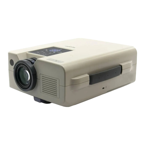
Part Names For details on the use of each control and terminal, refer to the page number indicated in the brackets. Projector Front View Zoom knob [p. 11] Focus knob [p. 11] Remote control sensor [p. 8] Carrying handle [p. 32] Kensington Security Standard connector [p. -
Page 8: Wireless Mouse Remote Control
Part Names Wireless Mouse Remote Control Front View Side View TRANSMIT MUTE button indicator MAIN POWER switch [p. 13] [pp. 8, 9] MUTE POWER buttons VOLUME buttons LEFT-CLICK button (ON/OFF) ( / ) [p. 13] [p. 9] [pp. 11, 13, 30, 31] LASER POINTER/ LASER BLACK... -
Page 9: Operating The Wireless Mouse Remote Control
Part Names Remote control and remote mouse receiver Transmission range Reception range positioning The remote control can be used to control the projec- Max. distance: 23 (7 m) tor in the ranges shown on the left. Projector The remote mouse receiver can be used with the remote control in the ranges shown to control the 30˚... - Page 10 "COMPLIES WITH 21 CFR SUBCHAPTER J" CAUTION SHARP ELECTRONICS CORPORATION The laser pointer on the remote control emits a laser SHARP PLAZA, MAHWAH, NEW JERSEY 07430 TEL : 1-800-BE-SHARP U.S.A. ONLY LASER RADIATION- beam from the laser light window. This is a Class II...
-
Page 11: Setting Up The Projector (Standard Setup)
Setting Up the Projector (Standard Setup) Optimal image quality can be achieved when the projector is positioned perpendicular to the screen with all feet flat and level. • Position the screen so that it is not in direct sunlight or room light. Light falling directly onto the screen washes out colors, making viewing difficult. -
Page 12: Basic Operations
Basic Operations a. Connecting the Power Cord Plug the supplied power cord into the AC socket on the back of the projector. b. Turning on the Main Power Press the MAIN POWER switch on the back of the projector. The POWER indicator lights up red and the projector enters standby mode. -
Page 13: Selecting The Video Input System Mode
Basic Operations g. Selecting the Video Input System Mode The video input system mode is set to “AUTO” at the factory; however, it can be changed to a different system mode, if the selected system mode is not compatible with the connected audiovisual equipment (such as when a color image appears in black and white, etc.). -
Page 14: Checking The Input Mode
Basic Operations On-screen i. Checking the Input Mode Display Press INPUT SELECT on the projector or IN- PUT CHECK on the remote control. The current input mode will be displayed on the screen for 4 seconds. j. Adjusting the Volume Press VOLUME (VOL) on the projector or the remote control. -
Page 15: Using The Menu Screens
Using the Menu Screens This projector has two sets of menu screens that allow you to adjust the picture and various projector settings. These menu screens can be operated from the projector or the remote control with the following buttons. Remote control Projector MUTE... -
Page 16: Picture Adjustments
Picture Adjustments This projector’s picture is factory preset to standard settings. However, you can adjust it to suit your own prefer- ences by adjusting the four picture modes: “PICTURE”, “BRIGHT”, “RED” and “BLUE”. The adjustments can be stored in the “RGB1”, “RGB2” and “VIDEO” modes separately. (The following steps are used as an example in adjusting the picture in “RGB1 ADJ.”... -
Page 17: Computer Adjustments
Computer Adjustments When displaying computer patterns which repeat every dot (tiling, vertical stripes, etc.), interference may occur between the LCD pixels, causing flickering, vertical stripes, or contrast irregularities in portions of the screen. Should this occur, adjust “CLOCK”, “PHASE”, “H-POS” and “V-POS” for optimum computer image. On-screen Display a. -
Page 18: Initial Reset
Computer Adjustments • When connecting third party video cards and other Macintosh computers, set “MODE” to “ON” or “OFF” to select the correct display mode. • When the input signal is automatically detected or when there is no input signal, “MODE(---)” appears on the screen and the display mode cannot be changed. -
Page 19: Audio Adjustments
Audio Adjustments This projector’s audio is factory preset to standard settings. However, you can adjust it to suit your own prefer- ences by adjusting “TREBLE” and “BASS”. On-screen Display a. Displaying the “AUDIO” screen Press MENU to display the menu screen. Press ADJUSTMENT ∂/ƒ... -
Page 20: Checking The System Setup
Checking the System Setup This function allows you to check the current input signal and lamp usage time. On-screen Display a. Displaying the “SYSTEM SETUP” screen Press MENU to display the menu screen. Press R G B 1 A D J . R G B 1 I N P U T A D J . -
Page 21: Black Screen Function
Black Screen Function This function can be used to superimpose a black screen over a presentation image. Presentation Image a. Blacking out the image Press BLACK SCREEN on the projector or the remote control to black out the image. “BLACK SCREEN”... -
Page 22: Blue Screen Function (Video Mode Only)
Blue Screen Function (VIDEO mode only) This function can be used to display a blue screen when the video input terminal is not connected to anything, when the video equipment is turned off, or when no video signal is being input through the video input terminal. •... -
Page 23: Using The Reverse/Invert Image Function
Using the Reverse/Invert Image Function This projector is equipped with a reverse/invert image function which allows you to reverse or invert the pro- jected image. • This function is useful for the reversed image and ceiling-mount setups. See page 24 for these setups. On-screen Display a. -
Page 24: Relationship Between Projector Distance And Picture Size
Distance between lens and screen (L) Above is an illustration of maximum and minimum projection distances for the PG-D120U with a picture size of 100 inches (254 cm). Move the projector forward or backward if the edges of the image are distorted. -
Page 25: Reversed Image And Ceiling-Mount Setups
• Ceiling-mount is possible when using the optional ceiling-mount bracket. • Before mounting the projector, be sure to contact your nearest Authorized Sharp Industrial LCD Products Dealer or Ser- vice Center to obtain the manufacturer recommended ceiling mount bracket (sold separately). (AN-XGCM50 Ceiling Mount Bracket, AN-EP101AP Extension Tube for AN-XGCM50.) -
Page 26: Connecting A Computer
Connecting a Computer You can connect your projector to a computer for easy projection of full color computer images. See page 26 for details on the connections. Connecting the projector to the computer Connect one end of the supplied computer cable into the COMPUTER INPUT (1 or 2) port on the projector and the other end into the RGB signal output port (Monitor Out) on the computer. -
Page 27: Connecting To The Computer Input Port
Connecting a Computer Connecting to the Computer Input Port You can connect your projector to a computer for easy projection of full-color computer images. a. Connecting an IBM-PC (VGA, SVGA, Rear ports of the projector XGA) Series computer Computer input port 1,024 768 maximum resolution Plug one end of the supplied computer cable... -
Page 28: Connecting Video Equipment
Connecting Video Equipment You can connect your projector to a VCR, laser disk player or external audio components. CAUTION • Always turn off the projector while connecting to video equipment, in order to protect both the projector and the equip- ment being connected. -
Page 29: Air Filter Maintenance
• The air filters should be cleaned every 100 hours of use. Clean the filters more often when the projector is used in a dusty or smoky location. • Have your nearest Authorized Sharp Industrial LCD Products Dealer or Service Center exchange the filter (PFILD0076CEZZ) when it is no longer possible to clean it. -
Page 30: Lamp/Maintenance Indicators
(See page 28.) • Cooling fan breakdown. • Take the projector to your nearest Autho- • Internal circuit failure. rized Sharp Industrial LCD Products Dealer or Service Center for repair. • Burnt-out lamp. • Carefully replace the lamp. (See pages 30... -
Page 31: Replacing The Projection Lamp
Indicators” on page 29.) The lamp usage time can be checked with the On-screen Display (see page 19). If the new lamp does not light after replacement, take your projector to the nearest Authorized Sharp Industrial LCD Products Dealer or Service Center for repair. Purchase a replacement lamp unit (lamp/cage module) of the current type BQC-XGNV4SU/1 from your nearest Authorized Sharp Industrial LCD Products Dealer or Service Center. -
Page 32: Using The Kensington Lock
Replacing the Projection Lamp Resetting the lamp timer • Reset the lamp timer only after replacing the lamp. Connect the power Reset the lamp timer. cord. Plug the power cord into the AC While pressing ADJUSTMENT “LAMP 0000H” is displayed, in- socket of the projector. -
Page 33: Transporting The Projector
Transporting the Projector When transporting the projector, carry it by the carrying handle on the side of the projector. Using the Carrying Handle CAUTION • Always put on the lens cap to prevent damage to the lens when transporting the projector. •... -
Page 34: Connection Pin Assignments
Connection Pin Assignments Analog Computer 1 and 2 Signal Input Computer Input Analog Ports: 15-pin mini D-sub female connector 1. Video input (red) 9. Not connected 2. Video input (green) 10. GND 3. Video input (blue) 11. GND 4. Reserve input 1 12. - Page 35 RS-232C Port Specifications Commands EXAMPLE • When “BRIGHT” of RGB 1 IMAGE ADJUSTMENT is set to Computer Projector → ← • If a dash (_) appears in the parameter column, enter a space. If an asterisk (*) appears, enter a value in the range indicated in brackets under CONTROL CONTENTS.
-
Page 36: Input Signals (Recommended Timing)
Input Signals (Recommended Timing) The computer output signal timing of different types of computer signals are shown below for reference. For IBM and compatibles For Macintosh Series VIDEO SIGNAL VIDEO SIGNAL HORIZONTAL SYNC SIGNAL C-SYNC(H) VIDEO SIGNAL VERTICAL e = 2 dot SYNC SIGNAL VIDEO SIGNAL C-SYNC(V) -
Page 37: Specifications
(QCNW-4870CEZZ), Air filter (PFILD0076CEZZ), Lens cap (GCOVH1307CESA), Power cord (QACCU5013CEZZ) This SHARP projector uses LCD (Liquid Crystal Display) panels. This will not affect the picture quality or the life expectancy of the These very sophisticated panels contain 485,616 pixels ( RGB) unit. -
Page 38: Dimensions
Dimensions Rear View Top View (19) (84) (84) (22) (43) 2 (62) Side View (70) (243.5) (77) (229) (10.5) Front View (25) (11) Bottom View Units: inches (mm) E-37... - Page 39 Notes E-38...
- Page 40 SHARP CORPORATION OSAKA, JAPAN Printed in Japan Imprimé au Japon Impreso en Japón TINS - 6764CEZZ T2143 - A 9P05 - JWG...
Need help?
Do you have a question about the PG-D120U and is the answer not in the manual?
Questions and answers