Table of Contents
Advertisement
Quick Links
I N S T A L L A T I O N M A N U A L
I N V I S I B L E S P E A K E R I S 4 C
TABLE OF CONTENTS
SONANCE and the SONANCE Logo are trademarks of Dana Innovations. ©2017 Dana Innovations. All rights reserved.
SONANCE.COM
2-3
2-3
4
4
5 - 8
9-11
12-16
17
18
1
Advertisement
Table of Contents

Related Manuals for Sonance IS4 C


Summary of Contents for Sonance IS4 C
-
Page 1: Table Of Contents
NE W CONSTRUC TION 5 - 8 E XISTING CONSTRUC TION 9-11 FINISHING INSTRUC TIONS 12-16 NOTES WA R R A NT Y SONANCE.COM SONANCE and the SONANCE Logo are trademarks of Dana Innovations. ©2017 Dana Innovations. All rights reserved. -
Page 2: Introduc Tion: Invisib Le Spe A Ke R Is 4 C
SONANCE INVISIBLE SERIES IS4 C The IS4 C is for any commercial or residential settings where a 70 or 100 volt system is being used. The IS4 C features all the industry standard tap settings as well as an 8-ohm bypass. - Page 3 After selecting a given tap, play the speaker with an actual audio signal to verify the speaker provides adequate volume. If necessary, re-select a lower or higher tap setting. POWER SELECT 100V (WATTS) IS4 C Speakers IS4 C Wiring Diagram Amplifier...
-
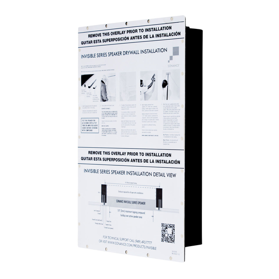
Page 4: Is 4 C Spe A Ke R Insta Ll Ation De Ta Il Vie W
Drywall Screw (speaker) IN-WALL-IN-CEILING/INVISIBLE-SERIES Note: IMPORTANT CONSIDERATION FOR LOCATING THE IS4 C ON WALLS For wall installations, locate the bottom of the Invisible Series Speaker at least 7 ft. (2.1m) up from the floor. Placing the speaker lower on the wall will put it at risk for having picture nails or other hanging devices driven through the diaphragm and damaging the speaker. -
Page 5: New Construction
Ensure the speaker cable will have easy access once the space saver is removed. IS4 C Space Saver Part Number: 92723 2. Place space saver in desired final location of speaker. 4. Secure edges of the space saver. - Page 6 NEW CONSTRUCTION 5. After all drywall is hung, begin speaker installation by removing space saver. 6. Be careful not to damage the exposed drywall during space saver removal.
- Page 7 NEW CONSTRUCTION 7. Pull 2-conductor speaker wire down into the 9. Peel off corresponding adhesive backing. exposed opening. 8. Select the appropriate shim for the application.* 10. Press shim firmly into position, aligning screw holes. Use cardboard shims for fine tuning. TALL SIDE 5/8”...
- Page 8 (Speaker shown with optional enclosure.) side. Top and bottom are optional. Do not over tighten. TEST THE SPEAKER FOR 60 SECONDS WITH IS4 C Space Saver Part Number: 92723 AN AUDIO SOURCE BEFORE COVERING WITH DRYWALL COMPOUND! This is the last point any wiring corrections can be made.
-
Page 9: E Xisting Construc Tion
EXISITNG CONSTRUCTION Using a utility knife, cut the drywall along the vertical Determine the location for the speaker. marks at the centers of the studs/ joists. Use the Using a stud finder, locate the first studs/joists to utility knife to complete the horizontal cuts at each the right and left of the speaker position. - Page 10 EXISITNG CONSTRUCTION 9. Pull 2-conductor speaker wire down into the 11. Peel off corresponding adhesive backing. exposed opening. 10. Select the appropriate shim for the application.* 12. Press shim firmly into position, aligning screw holes. Use cardboard shims for fine tuning. TALL SIDE 5/8”...
- Page 11 Top and bottom is optional. Do not over tighten. TEST THE SPEAKER FOR 60 SECONDS WITH IS4 C Space Saver Part Number: 92723 AN AUDIO SOURCE BEFORE COVERING WITH DRYWALL COMPOUND! This is the last point any wiring corrections can be made.
-
Page 12: Finishing Instructions
FINISHING INSTRUCTIONS 1. Fill the gap between speaker and drywall with 5 minute 3. Allow hot mud to set slightly before applying setting type joint compound (hot mud). mesh tape. 2. Feather all edges. - Page 13 FINISHING INSTRUCTIONS 4. Place mesh tape over the drywall seams. 6. Do not tape over the raised portion of the speaker (diaphragm). 7. Allow hot mud to fully cure or harden. 5. Overlap tape slightly.
- Page 14 FINISHING INSTRUCTIONS 10. Feather in all surfaces. 8. Once hot mud has fully cured or hardened, begin to Build layers of topping compound over speaker. 9. Build layers of compound as needed to obtain a flat surface. 11. Allow first coat to fully cure or harden.
- Page 15 FINISHING INSTRUCTIONS 12. Start a second coat covering the entire surface of 14. Detail the compound to minimize tool marks. the speaker and all adjoining surfaces. 13. Compound buildup on the active surface of the speaker 15. Build more coats as necessary to achieve desired finish. should not exceed 1/8”...
- Page 16 FINISHING INSTRUCTIONS 16. Each successive coat should be thinner than the last. The final coat should be a very light application (skim coat). 17. After final coat is applied and has dried, use a manual pole sander or block sander on entire wall (do not use a power sander).
-
Page 17: Notes
NOTES:... -
Page 18: Wa R R A Nt Y
Sonance Dealer/Distributor and installed by a Sonance installer, will be free from defective workmanship and materials in the initial installation for the period stated below. Subject to the additional limitations stated below, Sonance will (a) at its option and expense during the warranty period, either repair the defect or replace the Product with a new or remanufactured Product or a reasonable equivalent, and (b) arrange at its reasonable expense to re-install the Product and prepare the surface of the speaker and/or mounting platform for finishing and nothing more.
Need help?
Do you have a question about the IS4 C and is the answer not in the manual?
Questions and answers