Table of Contents
Advertisement
Quick Links
Installation & Maintenance
Instructions MM-616
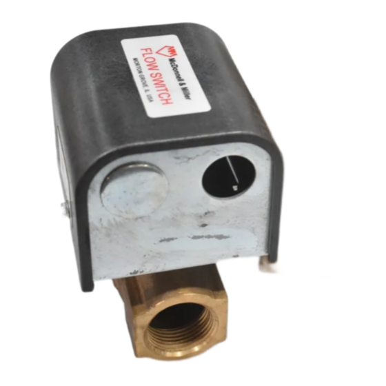
Series FS-5
General Purpose
Liquid Flow Switch
(specified models only)
OPERATION
This control is an independently mounted water flow
sensing device that makes or breaks an electrical
circuit when flow stops or starts.
• Before using product, read and understand instructions.
• Save these instructions for future reference.
• All work must be performed by qualified personnel trained in the proper application,
installation, and maintenance of plumbing, steam and electrical equipment and/or systems in
accordance with all applicable codes and ordinances.
• To prevent electrical shock, turn off the electrical power before making electrical
connections.
• To prevent an electrical fire or equipment damage, electrical wiring insulation must have a
rating of 167˚F (75˚C) if the liquid's temperature exceeds 180˚F (82˚C).
• To prevent electrocution, when the electrical power is connected to the flow switch, do not
touch the terminals.
• Make sure flow switch electrical cover is secured before turning on electric power.
Failure to follow this warning could cause property damage, personal injury or death.
®
!
WARNING
Series FS-5
Advertisement
Table of Contents

Related Manuals for Xylem FS-5


Summary of Contents for Xylem FS-5
- Page 1 Installation & Maintenance Instructions MM-616 Series FS-5 ® General Purpose Liquid Flow Switch (specified models only) Series FS-5 OPERATION This control is an independently mounted water flow sensing device that makes or breaks an electrical circuit when flow stops or starts.
-
Page 2: Specifications
SPECIFICATIONS Maximum Liquid Pressure: 150 psi (10.5 kg/cm Liquid Temperature Range (T ): 32 - 250˚F (0 - 121˚C) (All models except “S”) 32 - 225˚F (0 - 107˚C) (“S” models) Ambient Temperature Range (T ): 32 - 120˚F (0 - 49˚C) Electrical Enclosure Rating: Nema Type 1 (IP 21) Maximum Velocity: 10ft/sec (3M/sec) Pipe Connection Thread Size:... -
Page 3: Flow Rates
FLOW RATES Flow rates required to activate flow switch are shown Settings will vary when used to sense flow of other in chart below. The values are calculated for sensing fluids. water (potable, non-polluted) in a horizontal pipe. Flow Rates NOTE: DO NOT USE LIQUID FLOW Mode of Operation Max. - Page 4 SECTION 2 - Connecting the Flow Switch to Pipe ® a. Apply pipe sealing compound or Teflon tape to the pipe threads. NOTE: Do not apply sealant to first threads as this switch is grounded (earthed) via the pipe mounting. b.
-
Page 5: Step 3 - Electrical Installation
STEP 3 - Electrical Installation WARNING • To prevent electrical shock, turn off the electrical power before making electrical connections. • To prevent an electrical fire or equipment damage, electrical wiring insulation must have a rating of 167˚F (75˚C) if the liquid’s temperature exceeds 180˚F (82˚C). •... - Page 6 c. Determine which switch action is required for the flow switch. • “Flow” means that the switch will close circuit C.-N.O. and open circuit C.-N.C. when flow rate is increased above setpoint of flow switch. • “No Flow” means that the switch will open circuit C.-N.O.
- Page 7 STEP 4 - Testing a. Place cover on flow switch and turn on power. Initiate fluid flow through the system. Observe the device being activated by the flow switch to determine if device is operating as required. b. Turn off fluid flow to determine if device is operating as required.
-
Page 8: Maintenance
MAINTENANCE TROUBLESHOOTING Problem: SCHEDULE: • Inspect annually. Turbulent or high flow 1. Flow Switch Does Not Operate velocity conditions may require more frequent Solution: inspection and/or replacement. a. Make sure power has been turned on to device and flow switch. b.