Perlick HP48 Installation Manual
Hide thumbs
Also See for HP48:
- Service manual (125 pages) ,
- Operation & installation manual (38 pages) ,
- Installation instructions manual (16 pages)

Related Manuals for Perlick HP48


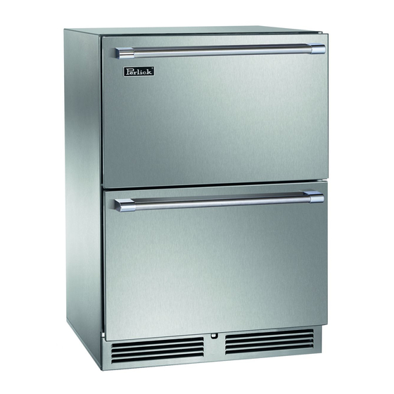
Summary of Contents for Perlick HP48
- Page 1 Installation Manual HP15 15” SIGNATURE SERIES HP24 24” SIGNATURE SERIES HP48 48” SIGNATURE SERIES HH24 SIGNATURE SERIES SOTTILE HC24 C-SERIES HA24 ADA-COMPLIANT SERIES Form No. Z2348-F Rev. 11.01.2017...
-
Page 2: Table Of Contents
(2) year period commencing on the date of purchase by the original retail purchaser if the We thank you again for selecting a high quality Perlick purchase of the product is not registered with Perlick product. We hope you enjoy using it. - Page 3 PERLICK RESIDENTIAL INSTALLATION MANUAL REMEDY: This Warranty does not apply to: Perlick will provide the parts and labor necessary to repair • Damage to Products occurring during transportation. or replace (at Perlick’s option) any parts proven to be • Products that are used in a manner that is not normal defective in material or workmanship during the Basic residential or light commercial use.
-
Page 4: Safety Information
Indicates a hazard MAY cause serious injury or death if precautions are not followed. All Perlick units come equipped with a NEMA 5-15P 90° plug with a 5’ cord extending beyond the rear of the cabinet. The electrical outlet must be flush with, or recessed into, CAUTION the wall surface for all HP, HC and HA models. -
Page 5: Installation Instructions
PERLICK RESIDENTIAL INSTALLATION MANUAL Serious Electrocution Hazard! NOTE: Anti-tip brackets are only used for stationary cabinets DANGER Electrical grounding is required. and should not be installed on cabinets with accessory casters. This appliance is equipped with a 3-prong (grounding) Caster kits are available for HP, HC and HA model cabinets. polarized plug for your protection against possible Refer to the instructions supplied with the caster kit for proper shock hazards. - Page 6 • Measure from the floor surface to the top of the unit at 35-1/2” maximum the rear corners. • Adjust the unit legs so these two measurements are HP48 48” Signature Series equal. Using an adjustable wrench or pliers, turn legs Height Depth Width clockwise to lower the unit or counterclockwise to raise it.
-
Page 7: Toe Kick Installation
PERLICK RESIDENTIAL INSTALLATION MANUAL TOE PLATE INSTALLATION Once the unit is secured in place, install the louvered toe plate. Secure the plate by snapping the latch into the latch catch on the unit (Figure 5). The toe plate must be removed to CAUTION service the unit. -
Page 8: Shelving/Drawer Adjustments
PERLICK RESIDENTIAL INSTALLATION MANUAL SHELVING/DRAWER ADJUSTMENTS DOOR OPTIONS Completely empty shelf or drawer Perlick residential units offer a variety of door panel design CAUTION before removing. alternatives; solid stainless steel, solid wood overlay, glass with stainless steel trim and glass with wood overlay trim. - Page 9 PERLICK RESIDENTIAL INSTALLATION MANUAL 5). Using the screws removed in step 3, install the top and bottom hinge brackets from the kit (Fig. 9). Figure 7. Door Removal Figure 9. Hinge Installation 6). Remove the top and bottom door hinge brackets and the push plunger brackets (Fig.
- Page 10 6 (Fig. 14). Figure 11. Removing Front Panel 8). Remove the Perlick nameplate from the door front using a plastic putty knife (Fig. 12). Install the new Perlick nameplate included in the kit. Figure 14. Door Hinges Figure 12.
-
Page 11: Handle Installation
DOOR LOCK INSTALLATION NOTE: Full size lock installation wood overlay panel templates Figure 15. Installing V-Block are available on the Perlick website. Visit www.perlick.com/ Residential, click on Service & Support, and then choose Wood Overlay Templates from the menu. Lock templates are 13). Lift the door assembly and insert the top pin into the available for all HP, HC, HA and HH series models. Take care in... -
Page 12: Wood Overlay Installation
PERLICK RESIDENTIAL INSTALLATION MANUAL WOOD OVERLAY INSTALLATION 3. In some cases, the dart on the gasket may rip. If this (FOR -2, -4 AND -6 MODELS) happens, replace with a new gasket. Before beginning installation, check all components for proper fit and finish. Handle should be installed to the overlay prior to installing overlay to door (use countersunk flathead fasteners for handle installation.) - Page 13 PERLICK RESIDENTIAL INSTALLATION MANUAL 5. Loosely attached the four corners of the overlay panel 7. After alignment is satisfied, fasten down all screws with the door frame with #10 x 3/4” wood screws. through the screw holes. Do not overtighten wood overlay...
-
Page 14: Wine Rack Trim
PERLICK RESIDENTIAL INSTALLATION MANUAL WINE RACK TRIM (OPTIONAL) 9. Verify that the gasket is fully seated onto the door frame when completed. All wine reserve racks come with sleek stainless steel fronts. Unfinished solid hardwood fronts are optional and can be removed and replaced with other wood to match your cabinetry. - Page 15 PERLICK RESIDENTIAL INSTALLATION MANUAL NOTES perlick.com...
- Page 16 Grilles, and Corresponding Compliance and Energy Guides are available for download at www.perlick.com/residential-products/service-support. Contact Perlick Customer or Technical Service at 800.558.5592. Customer Service and Technical Service are available business days Monday through Friday from 7:00 a.m. to 7:00 p.m. CST. 8300 W. Good Hope Road, Milwaukee, WI 53223 • 800.558.5592 • info@perlick.com • www.perlick.com Form No. Z2348-F Rev. 11.01.2017...
Need help?
Do you have a question about the HP48 and is the answer not in the manual?
Questions and answers