Table of Contents
Advertisement
Quick Links
Advertisement
Table of Contents

Related Manuals for Gefen USB-241


Summary of Contents for Gefen USB-241
- Page 1 USB•241 USER MANUAL...
-
Page 2: Table Of Contents
Front Panel Layout ... 6 Front Panel Function Description ... 7 Back Panel Layout ... 8 Back Panel Function Description ... 9 Monitor Dip Switch Settings ... 11 Front Panel Setting Descriptions ... 12-13 RMT-16 Remote Control ... 15 Wiring Diagrams ... 16-19 Link and RMT16 Cable ... - Page 3 20600 Nordhoff Street Chatsworth, CA 91311 USA www.gefen.com support@gefen.com Gefen Inc. reserves the right to make changes in the hardware, packaging and any accompanying documentation without prior written notice. USB•241 is a trademark of Gefen Inc. Macintosh is a trademark of Apple Computer Inc.
-
Page 4: Introduction
INTRODUCTION Thank you for purchasing Gefen Inc.’s ex•tend•it USB•241 KVM switcher series. The USB•241 switches your moni- tor and USB between two computers and is expandable up to 8 USB•241 units for a total of 16 computers. The USB•241 switcher is designed to be placed close to the computers. -
Page 5: Operation Notes
It is recommended to always leave the power of the USB•241 unit ON. 3. The monitor dip switch setting on the ex•tend•it USB•241 unit needs to be configured to the type of monitor used. Incorrect dip switch setting will result in no picture or incorrect picture size upon start up of the computer. -
Page 6: Installation
INSTALLATION 1. Plug the 17v power supply into “POWER” on the back of the USB•241 then plug the power supply into the wall. 2. Plug the supplied VGA cable into your first computer and plug the supplied USB cable into your first computer then plug both cables into “MON1”... - Page 7 USB•241 FRONT PANEL...
-
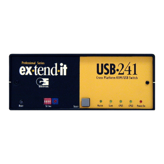
Page 8: Front Panel Function Description
Setting The four dip switches set up the USB•241 switching configuration. Page 11 for details. Unit Switch The rotary switch lets you control up to 8 USB•241 units. Refer to page 12 & 13 for more details. Selector Switch This switch allows you to toggle between CPUs. - Page 9 USB•241 BACK PANEL...
-
Page 10: Back Panel Function Description
BACK PANEL FUNCTION DESCRIPTIONS Remote connector RJ-11 connector for remoting the RMT-16 remote control Expansion DB-25 conncetor type, allows expansion with additional USB•241 units USB output Dual type A connector, supports two USB devices Monitor out HD-15 female connector which interfaces to your monitor. -
Page 11: Monitor Dip Switch Settings
Monitors. Horiz. Scan Rate: 75KHz Dip Switches 3, 6 & 7 ON Use for multi res (1920x 1080) monitors. Horiz. Scan Rate: 75KHz All Dip Switches set to OFF Use for Multi res monitor switch DDC Horiz. Scan Rate: 75KHz... -
Page 12: Front Panel Setting Descriptions
MASTER MODE Master mode: is used when controlling multiple USB•241 units using the front panel selector switch. The rotary switch is set to the unit number of USB•241 units used. SLAVE MODE Slave mode: is used when controlling multiple USB•241 units. - Page 13 USB•241 units with the RMT-16 unit. CLOSURE MODE Closure mode: is used with one USB•241 unit to switch between CPU-1 and CPU-2 using the remote input to switch. Refer to page 18 for more details REMOTE MODE Remote mode: Uses the RMT-16 unit to control switching between CPUs.
-
Page 14: Rmt16 Remote Control
RMT16 REMOTE CONTROL RMT16 F UNCTION RJ-11 Modular Jack Interface to the USB•241 remote input. Selector Switch Sets the counter limit from 1 to 16. Display Window Shows the current CPU selected. Up Arrow Up button increments the number showing in the display window. -
Page 15: Wiring Diagrams
2 CPU - 1 LOCAL - WIRING DIAGRAM... - Page 16 2 CPU - 1 LOCAL W/REMOTE...
- Page 17 2 CPU - 1 LOCAL W/CLOSURE...
- Page 18 4 CPU - LOCAL W/REMOTE...
-
Page 19: Link And Rmt16 Cable
LINK AND RMT16 CABLE... -
Page 20: Specifications
SPECIFICATIONS Video Amplifier bandwidth ... 350 MHz Actual Bandwidth ...120 MHz Input Video Signal ... 1.2 volt p-p (TTL) Input Sync Signal ... 5 volts p-p (TTL) Horizontal Frequency Range ... 15-70 KHz Vertical Frequency Range ... 30 - 170 HZ Video Connector ... -
Page 21: Warranty
If the equipment fails because of such defects and Gefen Inc. is notified within one (1) year from the date of shipment, Gefen Inc. will, at its option, repair or replace the equipment, provided that the equipment has not been subjected to mechanical, electrical, or other abuse or modifications. - Page 22 This document was created with Win2PDF available at http://www.daneprairie.com. The unregistered version of Win2PDF is for evaluation or non-commercial use only.
Need help?
Do you have a question about the USB-241 and is the answer not in the manual?
Questions and answers