
Related Manuals for LD VIBZ 24DC


Summary of Contents for LD VIBZ 24DC
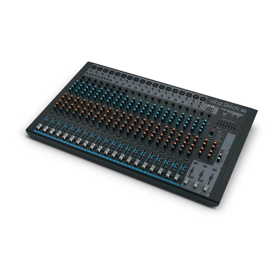
- Page 1 USER´S MANUAL BEDIENUNGSANLEITUNG MANUEL D`UTILISATION MANUAL DE USUARIO INSTRUKCJA OBSŁUGI MANUALE D‘ USO VIBZ 24DC 24-CHANNEL MIXING CONSOLE WITH DFX AND COMPRESSOR LDVIBZ24DC...
-
Page 2: Table Of Contents
CONTENTS / INHALTSVERZEICHNIS / CONTENU / CONTENIDO / TREŚĆ / CONTENUTO ENGLISH ESPAÑOL PREVENTIVE MEASURES MEDIDAS DE SEGURIDAD 56-57 INTRODUCTION INTRODUCCIÓN QUICK START GUIDE WITH CABLING EXAMPLE GUÍA RÁPIDA DE CABLEADO CONNECTIONS, CONTROLS AND INDICATORS 6-16 CONEXIONES, CONTROLES E INDICADORES 59-69 MONO CHANNELS 1-16 CANALES MONO 1-16... -
Page 3: Preventive Measures
ENGLISH You‘ve made the right choice! We have designed this product to operate reliably over many years. Please read this User‘s Manual carefully, so that you can begin making optimum use of your Cameo Light product quickly. Learn more about Cameo Light on our website WWW.CAMEOLIGHT.COM. PREVENTIVE MEASURES 1. -
Page 4: Introduction
CAUTION: To reduce the risk of electric shock, do not remove cover (or back). There are no user serviceable parts inside. Maintenance and repairs should be exclusively carried out by qualified service personnel. The warning triangle with lightning symbol indicates dangerous uninsulated voltage inside the unit, which may cause an electrical shock. -
Page 5: Quick Start Guide With Cabling Example
QUICK START GUIDE WITH CABLING EXAMPLE 1. Make sure that the mixer and all devices to be connected to the mixer are turned off. 2. Connect the devices to the mixer using appropriate cables. 3. Adjust the input gain of all the channels and all volume controllers for channels 1 to 23/24 and MAIN MIX to minimum. Place all equalizer con- trollers in the central position (stop). -
Page 6: Connections, Controls And Indicators
CONNECTIONS, CONTROLS AND INDICATORS POWER CONNECTOR WITH FUSE HOLDER IEC power socket with built-in fuse holder. An appropriate power cord is included in the delivery. IMPORTANT INFORMATION: Always replace the fuse only with a fuse of the same type with the same rating (printed on the device). If the fuse blows repeatedly, please contact an authorised service centre. -
Page 7: Mono Channels
AUX SEND 1-4 Unbalanced mono line outputs with 6.3 mm jack sockets to control an external effects device (POST Fader), or an active stage monitor (PRE Fader). INSERT CH1 - CH8 3-pin 6.3 mm jack sockets for inserting an external signal processing device (Compressor, Gate, etc.) in the corresponding channels 1 to 8. - Page 8 EQUALIZER MID CHANNEL 1-16 Equalizer mid band for channels 1 to 16 (adjustable frequency, +/-15 dB). When turned to the left, levels are lowered, when turned to the right, they are raised. In the centre position (resting point), the equalizer is inactive.
- Page 9 CLIP-LED CHANNEL 1-16 Once the red Clip LED lights up, the corresponding channel is operating at the distortion limit. Adjust the Gain controller (N 18) so that the Clip LED of the corresponding channel only lights up briefly when signal peaks occur. Avoid the permanent lighting of the Clip LED by reducing the input gain or input sensitivity;...
-
Page 10: Stereo Channels 17/18
STEREO CHANNELS 17/18 AND 19/20 MIC CHANNEL 17/18 AND 19/20 Balanced inputs of the channels 17/18 and 19/20 with 3-pin XLR sockets for connecting microphones. Channels 17/18 and 19/20 can be used as both mono and stereo channels, depending on the incoming signal (XLR and jack L IN = Mono / jack L and R IN = Stereo). - Page 11 AUX 1 + AUX 2 PRE/POST CHANNEL 17/18 AND 19/20 When using AUX 1 or AUX 2 to control an external effects device, bring the switch to the down position POST. The control signal is now picked up after the channel volume controller (N 53), it is therefore dependent on the latter. To control a stage monitor, bring the switch to the up position PRE.
-
Page 12: Stereo Channels 21/22
PFL CHANNEL 17/18 AND 19/20 Press down on the PFL switch (Pre Fader Listening) firstly, to be able to listen to the signal of the respective channel regardless of the channel level controller (N 53) using headphones connected to the headphone jack PHONES (N 82), secondly, to make a more accurate gain adjustment since the level of the input signal is now displayed on the 12-segment LED display of the MAIN MIX sum channel. - Page 13 AUX 3 POST CHANNEL 21/22 AND 23/24 Volume controller for adding the signal from channel 21/22 and 23/24 to an external effects device (Effect Send, Post Fader). Use the line output AUX SEND 3 (N 12) for activation. LEVEL DFX / AUX 4 POST CHANNEL 21/22 AND 23/24 Volume controller for adding the signal from channel 21/22 and 23/24 to the internal digital effects device (effect send, post fader).
-
Page 14: Master Section
MASTER SECTION POWER LAMP USB-socket type A to connect a desk lamp. Make sure that the specifications of the socket and the desk lamp match (5 V DC, a maximum of 500 mA). HEADPHONE OUTPUT 6.3 mm jack socket for connecting a headphone. This connection allows you to listen to various signals: A. - Page 15 SEND AUX 1 AND AUX 2 Volume controller for the sum signal from the input channels 1 to 23/24 routed via the AUX1 and AUX2 volume controllers. SEND AUX 3 Volume controller for the sum signal from the input channels 1 to 23/24 routed via the AUX3 level controller. SEND AUX 4 / DFX Volume controller for the sum of the signals from the input channels 1 to 23/24 (external or internal effects device) routed via the AUX4 / DFX level controller (N ...
-
Page 16: Instalation Of The Usb Interface
GROUP 1/2 L-R Volume controller for routing the group signal GROUP 1/2 to the MAIN MIX sum channel (down position). GROUP 3/4 Volume controller for the line outputs GROUP OUT 3 and 4 (N 11) and for adding the group signal GROUP 3/4 to the MAIN MIX sum channel, when the switch GROUP 3/4 L-R is pressed down (N ... -
Page 17: Specifications
SPECIFICATIONS Model Name: LDVIBZ24DC Product Type: analogue mixer Type: live / home recording Number of Channels: Mono Channels: Mono Mic/Line Input Channels: Mono Mic/Line Input Connections: 6.3 mm stereo jack, XLR Mono Mic Input Type: electronically balanced, discreet design Frequency Response Mono Mic Input: 10 - 45,000 Hz Amplification Range Mono Mic Input: 50 dB... - Page 18 Stereo Channels: Stereo Line Input Channels: Stereo Line Input Channels: 2 x 6.3 mm stereo jack (L mono, R) 2 x RCA (cinch) Stereo Line Input Type: unbalanced USB In/Out -Connection: USB type B (channel 21/22) Frequency Response Stereo Line Input: 10 - 45,000 Hz Amplification Range Stereo Line Input: 50 dB...
-
Page 19: Manufacturer´s Declarations
Specifications: Display Elements: Channel CLIP, Channel Signal, Channel PFL, Effect CLIP, DFX LED Display, Power, Phantom Power, 2x 12-segment level meter, Mute LEDs Connection for desk lamp: USB-A socket, 5 V DC, max. 500 mA USB In/Out: USB 2.0, 16 Bit Delta-Sigma DA: 32 kHz, 44,1 kHz, 48 kHz AD: 8 kHz, 11.025 kHz, 16 kHz, 22.05 kHz, 32 kHz, 44.1 kHz, 48 kHz Power Connector:... -
Page 20: Deutsch
DEUTSCH Sie haben die richtige Wahl getroffen! Dieses Gerät wurde unter hohen Qualitätsanforderungen entwickelt und gefertigt, um viele Jahre einen reibungslosen Betrieb zu gewährleisten. Bitte lesen Sie diese Bedienungsanleitung sorgfältig, damit Sie Ihr neues Produkt von Cameo Light schnell und optimal einsetzen können. Weitere Informationen über Cameo Light erhalten Sie auf unserer Website WWW.CAMEOLIGHT.COM. -
Page 21: Einführung
34. Der Abstand zu brennbaren Materialien muss mindestens 0,5 m betragen 35. Netzleitungen zur Spannungsversorgung mehrerer Geräte müssen mindestens 1,5 mm² Aderquerschnitt aufweisen. In der EU müssen die Leitungen H05VV-F, oder gleichartig, entsprechen. Geeignete Leitungen werden von Adam Hall angeboten. Mit diesen Leitungen können Sie mehrere Geräte über den Power out Anschluss mit dem Power IN Anschluss eines weiteren Gerätes verbinden. -
Page 22: Schnellstartanleitung Mit Verkabelungsbeispiel
SCHNELLSTARTANLEITUNG MIT VERKABELUNGSBEISPIEL 1. Achten Sie darauf, dass das Mischpult und alle Geräte, die am Mischpult angeschlossen werden sollen, ausgeschaltet sind. 2. Schließen Sie die Geräte mit geeigneten Kabeln am Mischpult an. 3. Stellen Sie die Vorverstärkung aller Kanäle und alle Pegelsteller Kanal 1 bis 23/24 und MAIN MIX auf Minimum. Bringen Sie die Regler aller Equalizer in Mittelstellung (Rastpunkt). -
Page 23: Anschlüsse, Bedien- Und Anzeigeelemente
ANSCHLÜSSE, BEDIEN- UND ANZEIGEELEMENTE NETZBUCHSE UND SICHERUNGSSCHALTER IEC Netzbuchse mit integriertem Sicherungshalter. Ein geeignetes Netzkabel befindet sich im Lieferumfang. WICHTIGER HINWEIS: Ersetzen Sie die Sicherung ausschließlich durch eine Sicherung des gleichen Typs und mit gleichen Werten entsprechend des Aufdrucks auf dem Gerät! Sollte die Sicherung wiederholt auslösen, wenden Sie sich bitte an ein autorisiertes Servicezentrum. POWER ON/OFF Ein- / Ausschalter für die Spannungszufuhr des Geräts (ON = eingeschaltet). - Page 24 CTRL ROOM Unsymmetrische Line-Ausgänge mit 6,3mm Klinkenbuchsen zum Anschließen von aktiven Abhör-Monitoren etc.. Ausgabe des Summen-Signals, oder der Gruppen-Signale 1-2, bzw. 3-4 des Mischpults, oder des PFL-Signals (umschaltbar). GROUP OUT 1-4 Unsymmetrische Line-Ausgänge mit 6,3mm Klinkenbuchsen zum Anschließen von aktiven Beschallungsanlagen etc.. Ausgabe der Gruppen-Signale 1 bis 4 des Mischpults.
-
Page 25: Mono-Kanäle
MONO-KANÄLE 1-16 MIC KANAL 1-16 Symmetrische Eingänge der Kanäle 1 bis 16 mit 3-Pol XLR-Buchsen zum Anschließen von Mikrofonen. Für den Betrieb von Kondensator-Mikrofonen steht eine 48V Phantomspeisung zur Verfügung, die zentral auf die XLR-Buchsen zugeschaltet werden kann (Nr. 3). Vor dem Ein- bzw. Ausstecken von Mikrofonen stellen Sie den Gain-Regler (Nr. - Page 26 EQ ON / OFF KANAL 1-16 Schalter zum Ein- und Ausschalten des Equalizers (HI, MID und LOW). In heruntergedrückter Position ist der Equalizer aktiviert, in nicht heruntergedrückter Position deaktiviert. AUX 1 + AUX 2 KANAL 1-16 Pegelsteller für die Zumischung des Signals von Kanal 1 bis 16 auf externe Effektgeräte (Effekt Send, Schalter Nr.
- Page 27 GR 1/2 KANAL 1-16 Bringen Sie den GR 1/2-Schalter in die heruntergedrückte Position, um den entsprechenden Kanal zur Kanal-Gruppe 1 (PAN auf Linksanschlag), zur Kanal-Gruppe 2 (PAN auf Rechtsanschlag), oder mit den gleichen Signalanteilen zu beiden Kanal-Gruppen 1 und 2 (PAN in Mittelstellung) hinzuzufügen.
-
Page 28: Stereo-Kanäle 17/18 & 19/20
STEREO-KANÄLE 17/18 & 19/20 MIC KANAL 17/18 & 19/20 Symmetrische Eingänge der Kanäle 17/18 und 19/20 mit 3-Pol XLR-Buchsen zum Anschließen von Mikrofonen. Die Kanäle 17/18 und 19/20 können je nach Belegung sowohl als Mono- als auch als Stereo- Kanäle verwendet werden (XLR und Klinke L IN = Mono / Klinke L und R IN = Stereo). Für den Betrieb von Kondensator-Mikrofonen steht eine 48V Phantomspeisung zur Verfügung, die zentral auf die XLR-Buchsen zugeschaltet werden kann (Nr. - Page 29 AUX 3 POST KANAL 17/18 & 19/20 Pegelsteller für die Zumischung des Signals von Kanal 17/18 und 19/20 auf ein externes Effektgeräte (Effekt Send, Post Fader). Verwenden Sie den Line-Ausgang AUX SEND 3 (Nr. 12) zur Ansteuerung. LEVEL DFX / AUX 4 POST KANAL 17/18 & 19/20 Pegelsteller für die Zumischung des Signals von Kanal 17/18 und 19/20 auf das interne digitale Effektgerät (Effekt Send, Post Fader).
-
Page 30: Stereo-Kanäle 21/22 & 23/24
Um einen Eingangskanal (Kanal 17/18 und 19/20) direkt auf den Summen-Kanal MAIN MIX zu routen, bringen Sie den Schalter L-R des entspre- chenden Kanals in die heruntergedrückte Position. PFL KANAL 17/18 & 19/20 Bringen Sie den PFL-Schalter (Pre Fader Listening) in die heruntergedrückte Position, erstens, um das Signal des entsprechenden Kanals unabhängig vom Kanal-Pegelsteller (Nr. - Page 31 Wenn Sie AUX 1 bzw. AUX 2 zur Ansteuerung eines externen Effektgeräts verwenden, bringen Sie den Schal- ter in die heruntergedrückte Position POST. Das Ansteuerungsignal wird nun hinter dem Kanal-Pegelsteller (Nr. 74) abgegriffen, ist also abhängig davon. Zur Ansteuerung eines Bühnenmonitors, bringen Sie den Schalter in die nicht heruntergedrückte Position PRE.
- Page 32 nal-Gruppe 3 (BAL auf Linksanschlag), zur Kanal-Gruppe 4 (BAL auf Rechtsanschlag), oder mit den gleichen Signalanteilen zu beiden Kanal-Grup- pen 3 und 4 (BAL in Mittelstellung) hinzuzufügen. Gleichzeitig werden die Signale der in eine Gruppe zusammengefassten Kanäle auf die entsprechenden Line-Ausgänge GROUP OUT 3/4 geroutet.
-
Page 33: Master-Sektion
MASTER-SEKTION POWER LAMP USB-Buchse Typ A zum Anschließen einer Pult-Lampe. Achten Sie darauf, dass die Spezifikationen des Anschlusses und der Pult-Lampe übereinstimmen (5V DC, maximal 500mA). KOPFHÖRERAUSGANG 6,3mm Stereo-Klinkenbuchse zum Anschließen eines Kopfhörers. Dieser Anschluss ermöglicht das Wahlweise Abhören verschiedener Signale: A. - Page 34 DFX MUTE Um das interne Effektgerät stummzuschalten, drücken Sie kurz auf den DFX Mute-Taster und nochmals, um die Stummschaltung zu deaktivieren. Ist das Effektgerät stummgeschaltet, leuchtet die Peak-LED Nr. 90 permanent. SEND AUX 1 & AUX 2 Pegelsteller für das Gesamt-Signal der über die AUX 1 und AUX 2 Pegelsteller ausgespielten Signale der Eingangskanäle 1 bis 23/24. SEND AUX 3 Pegelsteller für das Gesamt-Signal der über die AUX 3 Pegelsteller ausgespielten Signale der Eingangskanäle 1 bis 23/24.
-
Page 35: Installation Usb-Schnittstelle
GROUP 1/2 Pegelsteller für die Line-Ausgänge GROUP OUT 1 und 2 (Nr. 11) und für die Zumischung des Gruppen-Signals GROUP 1/2 zum Summen-Kanal MAIN MIX, wenn Schalter GROUP 1/2 L-R heruntergedrückt ist (Nr. 105). Stellen Sie vor dem Einschalten einer angeschlossenen Beschallungsanlage den Pegelsteller auf Minimum. -
Page 36: Technische Daten
TECHNISCHE DATEN Modellbezeichnung: LDVIBZ24DC Produktart: Analoges Mischpult Typ: Live / Home recording Anzahl Kanäle: Mono Kanäle: Mono Mic/Line Eingangskanäle: Mono Mic/Line Eingangsanschlüsse: 6,3 mm Stereoklinke, XLR Mono Mic Eingangstyp: elektronisch symmetriert, diskreter Aufbau Frequenzgang Mono Mic Eingang: 10 - 45.000Hz Verstärkungsbereich Mono Mic Eingang: 50dB Kanalübersprechung:... - Page 37 Stereo Kanäle: Stereo Line Eingangskanäle: Stereo Line Eingangsanschlüsse: 2x 6,3 mm Stereoklinke (L mono, R) 2x RCA (Chinch) Stereo Line Eingangstyp: Unbalanced USB In/Out -Anschluß: USB-type B (Kanal 21/22) Frequenzgang Stereo Line Eingang: 10 - 45.000Hz Verstärkungsbereich Stereo Line Eingang: 50dB Kanalübersprechung: 62 dB...
-
Page 38: Herstellererklärungen
Generelle Spezifikationen: Anzeigeelemente: Kanal-CLIP, Kanal-Signal, Kanal-PFL, Effekt-CLIP, DFX LED-Display, Power, Phantom Power, 2x 12-Segment Pegel-Anzeige, Mute-LEDs Anschluss für Pultlampe: USB-A Buchse, 5VDC, max. 500mA USB In/Out: USB 2.0, 16 Bit Delta-Sigma DA: 32kHz, 44,1kHz, 48kHz AD: 8kHz, 11,025kHz, 16kHz, 22,05kHz, 32kHz, 44,1kHz, 48kHz Stromversorgungsanschluss: IEC Netzbuchse Betriebsspannung:... -
Page 39: Mesures Préventives
FRANCAIS Vous avez fait le bon choix! Cet appareil a été développé et fabriqué en appliquant des exigences de qualité très élevées: il garantit des années de fonctionnement sans problème.Veuillez lire attentivement ce Manuel Utilisateur : vous apprendrez rapidement à utiliser votre appareil Cameo Light de façon optimale. -
Page 40: Introduction
LDVIBZ24DC - Table de mixage 24 canaux avec multieffet numérique et compresseur La VIBZ 24DC est une table de mixage d’une grande polyvalence, équipée de 16 entrées micro symétriques intégrant des préamplis de haute qualité, un filtre passe-haut (Low-Cut), un égaliseur 3 bandes efficace avec médium semi-paramétrique et une alimentation fantôme commutable. -
Page 41: Guide De Prise En Main Rapide Avec Exemple De Câblage
GUIDE DE PRISE EN MAIN RAPIDE AVEC EXEMPLE DE CÂBLAGE 1. Vérifiez que la table de mixage et tous les appareils à lui connecter sont éteints. 2. Connectez les appareils à la table de mixage, à l’aide de câbles adaptés. 3. -
Page 42: Connecteurs, Contrôles Et Indicateurs
CONNECTEURS, CONTRÔLES ET INDICATEURS EMBASE SECTEUR ET PORTE-FUSIBLE Embase secteur au format IEC, avec porte-fusible intégré. Le câble secteur correspondant est livré. CONSEIL IMPORTANT : Remplacez exclusivement le fusible par un fusible neuf du même format et du même calibre (valeurs indiquées sur le panneau arrière de l’appareil). -
Page 43: Entrées Mono
GROUP OUT 1-4 Sortie stéréo/double mono (groupes 1 et 2) asymétrique au niveau ligne sur connecteurs jack 6,35 mm, pour connexion de retours de scène actifs etc. Sortie des signaux des groupes 1 à 4 de la console de mixage. AUX SEND 1-4 Sorties mono ligne asymétriques sur jacks 6,35 mm pour connexion d’un multieffet externe (POST Fader) ou de retours de scène actifs (PRE Fader). - Page 44 ÉGALISEUR HI VOIES 1-16 Égaliseur d’aigus pour les voies 1 à 16 (fréquence centrale 12 kHz, +/-15 dB). Tourner vers la gauche pour baisser les aigus, vers la droite pour les monter. En position centrale (crantée), le correcteur est inactif. ÉGALISEUR MID VOIES 1-16 Égaliseur de médiums pour les voies 1 à...
- Page 45 FADERS VOIES 1-16 Réglage de volume pour les voies d’entrée 1 à 16. Montez le fader pour augmenter le niveau sur la voie désirée, baissez le fader pour le réduire. LED SIGNAL VOIES 1-16 La LED SIGNAL s’allume dès qu’un signal audio est présent dans la voie correspondante (selon le niveau d’entrée et la position du potentiomètre GAIN de gain de préamplification ou de sensibilité...
-
Page 46: Voies Stéréo 17/18 Et 19/20
VOIES STÉRÉO 17/18 ET 19/20 VOIES MICRO 17/18 & 19/20 Entrées symétriques pour les canaux 17/18 et 19/20, sur embases XLR 3 points pour connexion de microphones. Les voies 17/18 et 19/20 s’utilisent aussi bien en mono qu’en stéréo (XLR ou jack L IN seul = mono / XLR ou jacks L et R IN = stéréo). - Page 47 AUX 1 + AUX 2 PRE/POST VOIES 17/18 & 19/20 Si vous désirez utiliser le départ AUX 1 ou 2 pour alimenter un multieffet externe, le sélecteur doit se trouver en position POST (touche enfoncée). Dans ce cas, le signal de départ auxiliaire est prélevé après son passage par le fader de la voie (n°53) : il est donc dépendant de la position du fader. Si vous désirez utiliser le départ AUX 1 ou 2 pour alimenter des retours de scène, le sélecteur doit se trouver en position PRE (touche non enfoncée).
-
Page 48: Voies Stéréo 21/22 Et 23/24
PFL VOIES 17/18 & 19/20 La touche PFL (Pre Fader Listening), activant l’écoute directe du signal de la voie avant passage par le fader, s’utilise dans deux cas : 1) pour vérifier le signal de la voie correspondante indépendamment de la position du fader (n°53), en écoutant sur un casque branché sur la sortie PHONES (n°82) ;... - Page 49 AUX 1 + AUX 2 PRE/POST VOIES 21/22 & 23/24 Si vous désirez utiliser les départs AUX 1 et 2 pour alimenter un multieffet externe, le sélecteur doit se trouver en position POST (touche enfoncée). Dans ce cas, le signal de départ auxiliaire est prélevé après son passage par le fader (n°74) de la voie : il est donc dépendant de la position du fader .
-
Page 50: Section Master
PFL VOIES 21/22 & 23/24 La touche PFL (Pre Fader Listening), activant l’écoute directe du signal de la voie avant passage par le fader, s’utilise dans deux cas : 1) pour vérifier le signal de la voie correspondante indépendamment de la position du fader (n°74), en écoutant sur un casque branché... - Page 51 LED PEAK DFX Dès que la LED rouge s’allume, c’est que l’entrée du multieffet interne est à la limite de la distorsion. Dans ce cas, baissez le niveau du bus de départ effet DFX SEND AUX 4 (n°94) de façon à ce que la LED Peak ne s’allume qu’occasionnellement sur les crêtes de signal. DFX MUTE Pour couper la sortie du multieffet interne, appuyez brièvement sur la touche DFX Mute ;...
- Page 52 NIVEAU CASQUE Réglage de volume pour la sortie casque (n°82). Utilisez un casque d’une impédance d’au moins 30 ohms, et veillez à ne pas dépasser un niveau d’écoute confortable, afin d’éviter tout dommage auditif. Avant de brancher votre casque, réglez le volume au minimum. GROUP 1/2 Réglage de volume du signal sur les sorties ligne GROUP OUT 1 et 2 (n°11) et de la réinjection du signal des groupes 1/2 sur les généraux (MAIN MIX) lorsque la touche GROUP 1/2 L-R est enfoncée.
-
Page 53: Installation Port Usb
INSTALLATION PORT USB Installation sous Windows (Windows XP® ou ultérieur) : Il n'est pas nécessaire d'installer des pilotes spécifiques, par téléchargement ou depuis un support de masse externe, pour pouvoir utiliser la console. Reliez la console, via le câble USB livré, à l'un des ports USB 2.0 de votre ordinateur. Dans la plupart des cas, l'installation du pilote logiciel nécessaire se lance alors automatiquement. - Page 54 Voies Stéréo : Nombre de Voies d'Entrée Ligne Stéréo : Connecteurs Entrée Ligne Stéréo : 2 x jack TRS 6,35 mm (L compatible mono, R), 2 x RCA/cinch Type Entrée Ligne Stéréo : asymétrique Port d’entrée/sortie USB : USB-type B (assigné aux voies 21/22) Réponse en Fréquence Entrée Ligne Stéréo : 10 Hz - 45 kHz Gain d'Entrée sur Entrée Ligne Stéréo :...
-
Page 55: Declarations
Caractéristiques Générales : Indicateurs : CLIP (écrêtage sur la voie), Signal (présence d'un signal sur la voie), CLIP Effet, Afficheur LED DFX, Power, alimentation fantôme, échelle 2 x 12 LED pour visualisation niveau généraux, LED Mute Connecteur pour lampe console : Port USB-A, tension continue 5 volts, intensité... -
Page 56: Español
ESPAÑOL ¡Gracias por elegir Cameo Light! Este equipo está diseñado y fabricado con los estándares de calidad más exigentes, para garantizar un correcto funcionamiento durante muchos años.Lea atentamente este manual de usuario para poder aprovechar rápidamente toda la funcionalidad de su nuevo producto de Cameo Light. -
Page 57: Introducción
33. La acumulación de polvo y otras partículas en el interior del equipo puede causar daños. Dependiendo de las condiciones ambientales (polvo, nicotina, niebla, etc.), deberá realizarse periódicamente el mantenimiento o la limpieza del equipo por personal especializado, para evitar cualquier sobrecalentamiento o fallo de funcionamiento (mantenimiento y limpieza no cubiertos por la garantía). 34. -
Page 58: Guía Rápida De Cableado
GUÍA RÁPIDA DE CABLEADO 1. Asegúrese de que están apagados la mesa de mezclas y todos los equipos conectados a la mesa de mezclas. 2. Conecte el equipo mediante los cables adecuados a la mesa de mezclas. 3. Ajuste al mínimo la ganancia de entrada de todos canales y todos los faders de los canales 1 a 23/24 y MAIN MIX. Sitúe todos los controles de ecualización en la posición media (se siente un clic). -
Page 59: Conexiones, Controles E Indicadores
CONEXIONES, CONTROLES E INDICADORES TOMA ELÉCTRICA Y PORTAFUSIBLES Toma IEC con portafusibles integrado. Se suministra con el cable eléctrico apropiado. NOTA IMPORTANTE: Sustituya el fusible únicamente por otro del mismo tipo y características serigrafiadas en el equipo. Si el fusible se fundiera continuamente, póngase en contacto con un servicio técnico autorizado. -
Page 60: Canales Mono
AUX SEND 1-4 Salida de línea mono no balanceada con jacks de 6,3 mm para enviar la señal a un procesador de efectos externo (POST fader) o un monitor activo de escenario (PRE fader). INSERT CH1 - CH8 Jacks estéreo de 6,3 mm para insertar un equipo externo que procese la señal (compresor, puerta de ruido, etc.) en uno de los canales 1 a 8. - Page 61 ECUALIZADOR MID FREQ (CANALES 1-16) Frecuencia de la banda de medios. Ajuste la frecuencia de 200 Hz a 8 kHz. ECUALIZADOR LOW (CANALES 1-16) Controles de graves de los canales 1 a 16 (80 Hz, +/-15 dB). Girar a la izquierda para disminuir los graves y a la derecha para realzarlos.
- Page 62 GR 1/2 (CANALES 1-16) Sitúe en la posición pulsada el botón GR 1/2 de un canal para añadirlo al grupo 1 de canales (PAN girado completamente a la izquierda), al grupo 2 de canales (PAN girado completamente a la derecha), o para enviar la misma señal a los grupos 1 y 2 a la vez (PAN en la posición intermedia). Además, se envía la señal de un grupo de canales a la salida de línea GROUP OUT 1/2.
-
Page 63: Canales Estéreo 17/18 Y 19/20
CANALES ESTÉREO 17/18 Y 19/20 MIC (CANALES 17/18 + 19/20) Entradas balanceadas de los canales 17/18 y 19/20 con XLR hembra de 3 pines para la conexión de micrófonos. Los canales 17/18 y 19/20 pueden emplearse como mono o como estéreo (XLR y jack L = entrada mono;... - Page 64 AUX 1 + AUX 2 PRE/POST (CANALES 17/18 + 19/20) Si está utilizando AUX 1 o AUX 2 para enviar la señal a un procesador de efectos externo, sitúe el botón en la posición pulsada POST. La señal dependerá ahora del fader de canal (53). Para enviar la señal al monitor de escenario, sitúe el botón en la posición PRE (sin pulsar).
-
Page 65: Canales Estéreo 21/22 Y 23/24
L-R (CANALES 17/18 + 19/20) Para enviar directamente un canal de entrada (canales 17/18 y 19/20) al canal de mezcla MAIN MIX, deje pulsado el botón de L-R del canal. PFL (CANALES 17/18 + 19/20) Pulse el botón PFL (Pre Fader Listen) de un canal, primero, para que a través de los cascos conectados a la salida de auriculares PHONES (82), nos llegue la señal de dicho canal independientemente de la posición del fader de canal (53) y, segundo, para realizar un ajuste preciso del a ganancia, ya que el nivel de la señal de entrada se mostrará... - Page 66 AUX 1 + AUX 2 PRE/POST (CANALES 21/22 + 23/24) Si está utilizando AUX 1 o AUX 2 para enviar la señal a un procesador de efectos externo, sitúe el botón en la posición pulsada POST. La señal dependerá ahora del fader de canal (74). Para enviar la señal al monitor de escenario, sitúe el botón en la posición PRE (sin pulsar).
-
Page 67: Sección Master
L-R (CANALES 21/22 + 23/24) Para enviar directamente un canal de entrada (canales 21/22 y 23/24) al canal de mezcla MAIN MIX, deje pulsado el botón de L-R del canal. PFL (CANALES 21/22 + 23/24) Pulse el botón PFL (Pre Fader Listen) de un canal, primero, para que a través de los cascos conectados a la salida de auriculares PHONES (82) nos llegue la señal de dicho canal independientemente de la posición del fader de canal (74) y, segundo, para realizar un ajuste preciso de la ganancia, ya que el nivel de la señal de entrada se... - Page 68 DFX PRESETS LIST Lista de los efectos digitales disponibles. LED PEAK DFX Si el LED PEAK de una entrada se ilumina de color rojo, la entrada del procesador interno de efectos está saturando. Ajuste el control de nivel de envío de efecto DFX SEND AUX 4 (94) de tal forma que el LED PEAK solo se ilumine brevemente en los picos de la señal entrante. DFX MUTE Para silenciar el procesador interno de efectos, pulse brevemente el botón MUTE DFX;...
- Page 69 NIVEL CTRL ROOM Control de volumen para la salida de línea estéreo de monitorado de sala CTRL ROOM (10). Antes de encender el altavoz de monitorado que haya conectado, sitúe este control al mínimo. NIVEL DE AURICULARES Control de volumen para los auriculares (82). Emplee unos auriculares con una impedancia mínima de 30 ohmios y asegúrese de mantener el volu- men en un nivel adecuado que evite daños auditivos debido a niveles sonoros altos.
-
Page 70: Instalación Del Puerto Usb
INSTALACIÓN DEL PUERTO USB Instalación en sistemas operativos Windows (Windows XP® o superior): Para la instalación no es necesario descargar ningún controlador en una unidad de almacenamiento externo. Conecte la mesa de mezclas mediante el cable USB suministrado a un puerto USB 2.0 del ordenador. Casi siempre, la instalación del software se realizará automáticamente. Si es necesario, reinicie el ordenador. - Page 71 Canales estéreo: Canales de entrada estéreo de línea: Conectores de entrada estéreo de línea: 2 jacks estéreo de 6,3 mm (L mono, R), 2 RCA (Cinch) Tipo de entrada estéreo de línea: No balanceada Conector de USB IN/OUT: USB tipo B (canales 21/22) Respuesta en frecuencia de la entrada estéreo 10 - 45.000 Hz de línea:...
-
Page 72: Declaración Del Fabricante
Especificaciones generales: Indicadores: LED de picos, señal y PFL en cada canal, picos en la sección de efectos, encendido, alimentación fantasma, Mute, pantalla LED DFX, vúmetro doble de 12 segmentos Conector para la lámpara: USB-A, 5 VDC, 500 mA máx. USB IN/OUT: USB 2.0, conversor Delta-Sigma de 16 bits D/A: 32 kHz, 44,1 kHz, 48 kHz A/D: 8 kHz, 11,025 kHz, 16 kHz, 22,05 kHz, 32 kHz, 44,1 kHz, 48 kHz... -
Page 73: Polski
POLSKI Gratulujemy wyboru! To urządzenie zostało zaprojektowane i wyprodukowane przy zastosowaniu najwyższych kryteriów jakościowych w celu zapewnienia wieloletniej bezawaryjnej eksploatacji. Proszę starannie przeczytać niniejszą instrukcję obsługi, aby móc jak najszybciej zacząć użytkować ten produkt marki Cameo Light. Więcej informacji na temat Cameo Light znajdą Państwo na naszej stronie internetowej pod adresem WWW.CAMEOLIGHT.COM. -
Page 74: Introduction
32. Instalacja urządzenia powinna odbywać się, gdy urządzenie nie jest podłączone do źródła zasilania (należy wyjąć wtyczkę z gniazda). 33. Kurz i inne osady wewnątrz urządzenia mogą je uszkodzić. W zależności od warunków otoczenia (kurz, nikotyna, opary itp.) urządzenie powinno być konserwowane lub czyszczone przez wykwalifikowanego specjalistę (usługa nieobjęta gwarancją), aby zapobiec przegrzaniu i nieprawidłowemu działaniu. -
Page 75: Instrukcja Szybkiego Uruchamiania Z Przykładowym Okablowaniem
INSTRUKCJA SZYBKIEGO URUCHAMIANIA Z PRZYKŁADOWYM OKABLOWANIEM 1. Upewnić się, że pulpit mikserski i wszystkie urządzenia, które mają zostać do niego podłączone, są wyłączone. 2. Podłączyć urządzenia do pulpitu mikserskiego za pomocą odpowiednich kabli. 3. Ustawić wstępne wzmocnienie wszystkich kanałów i wszystkich regulatorów poziomów sygnału kanałów od 1 do 23/24 i MAIN MIX na minimum. -
Page 76: Przyłącza, Elementy Obsługi I Wskaźniki
PRZYŁĄCZA, ELEMENTY OBSŁUGI I WSKAŹNIKI GNIAZDO SIECIOWE I UCHWYT BEZPIECZNIKOWY Gniazdo sieciowe IEC ze zintegrowaną podstawą bezpiecznika. W zestawie znajduje się odpowiedni kabel sieciowy. WAŻNA INFORMACJA: bezpiecznik należy wymieniać wyłącznie na bezpiecznik tego samego typu i o takich samych parametrach, zgodnie z nadrukiem na urządzeniu. -
Page 77: Kanały Mono
GROUP OUT 1–4 Niesymetryczne wyjścia liniowe wyposażone w gniazda jack 6,3 mm do podłączenia aktywnych systemów nagłośniających itd. Emitowanie grupy sygnałów od 1 do 4 z pulpitu mikserskiego. AUX SEND 1–4 Niesymetryczne monofoniczne wyjścia liniowe wyposażone w gniazda jack 6,3 mm do sterowania zewnętrznymi efektami w trybie (POST Fader) lub wyprowadzenia sygnału do aktywnych monitorów scenicznych w trybie (PRE Fader). - Page 78 COMP LED Wskaźnik LED świeci się tak długo, jak aktywny jest kompresor. EQUALIZER HI KANAL 1–16 Korektor dźwięku tonów wysokich kanałów od 1 do 16 (12 kHz, +/−15 dB). Obrót w lewo powoduje zmniejszenie poziomu tonów wysokich, a obrót w prawo jego zwiększenie. W pozycji środkowej (kliknięcie) korektor jest nieaktywny.
- Page 79 MUTE KANAL 1–16 W celu wyciszenia danego kanału należy upewnić się, że przycisk wyciszania MUTE odpowiedniego kanału znajduje się we wciśniętej pozycji. Po naciśnięciu przycisku wyciszania MUTE zapali się znajdująca się obok niego dioda. Po ponownym naciśnięciu dioda zgaśnie, sygnalizując dezaktywowanie wyciszenia.
-
Page 80: Kanały Stereo 17/18 I 19/20
KANAŁY STEREO 17/18 I 19/20 MIC KANAL 17/18 & 19/20 Symetryczne wejścia kanałów 17/18 i 19/20 wyposażone w 3-stykowe gniazda XLR do podłączenia mikrofonów. Kanały 17/18 i 19/20 mogą pełnić funkcję zarówno kanałów mono, jak i stereo, w zależności od podłączonych urządzeń (XLR i gniazdo jack L IN = mono/gniazdo jack L i R IN = stereo). Aby umożliwić pracę... - Page 81 AUX 1 + AUX 2 PRE/POST KANAL 17/18 & 19/20 Jeżeli sygnał wyprowadzany jest do zewnętrznego efektu za pomocą wyjścia AUX 1 lub AUX 2, należy upewnić się, że przycisk znajduje się we wciśniętej pozycji POST. Wyprowadzany w ten sposób sygnał będzie przechodził teraz przez regulator poziomu kanału (nr 53), w związku z czym jego poziom będzie zależny od ustawienia regulatora.
-
Page 82: Kanały Stereo 21/22 I 23/24
L-R KANAL 17/18 & 19/20 W celu przetrasowania kanału wejściowego (kanał 17/18 i 19/20) bezpośrednio na sumę kanałów MAIN MIX należy nacisnąć przycisk L–R odpowiedniego kanału (pozycja wciśnięta). PFL KANAL 17/18 & 19/20 W celu, po pierwsze, przeprowadzenia niezależnego od ustawienia regulatora poziomu kanału (nr 53) – od- słuchu kontrolnego sygnału danego kanału za pomocą... - Page 83 AUX 1 + AUX 2 KANAL 21/22 & 23/24 Regulatory poziomów sygnałów służące do dodawania sygnałów kanałów 21/22 i 23/24 na zewnętrzne efekty (wysyłka do efektu, przycisk nr 69 – POST) lub wyprowadzenia sygnału do monitorów scenicznych (wysyłka do monitora, przycisk nr 69 – PRE). Skorzystać z wyjść liniowych AUX SEND 1 i 2 (nr 12) w celu wyprowadzenia sygnału.
-
Page 84: Sekcja Master
GR 3/4 KANAL 21/22 & 23/24 W celu przypisania danego kanału do grupy kanałów 3 (regulatory BAL obrócone maksymalnie w lewo), grupy kanałów 4 (regulator BAL obrócony maksymalnie w prawo) lub równomiernego przydzielenia sygnału do obu grup kanałów 3 i 4 (regulator BAL w ustawieniu centralnym) należy nacisnąć... - Page 85 WSKAŹNIK LED +48 V Dopóki zasilanie phantom pulpitu mikserskiego jest włączone, wskaźnik LED +48 V świeci (przycisk nr 3 na tylnej ścianie). POWER-LED Dioda zasilania świeci, gdy system jest włączony i prawidłowo podłączony do sieci elektrycznej. DISPLAY DFX PRESET Dwuznakowy wyświetlacz LED do wskazywania numeru ustawień predefiniowanych danego efektu (00–99). DFX PRESETS (PUSH) Pokrętło-przycisk służący do wyboru i włączenia ustawień...
- Page 86 PFL-LED Dioda LED PFL zapala się, gdy jeden (lub więcej) przycisk PFL kanałów wejściowych od 1 do 23/24 zostanie wciśnięty. CTRL ROOM SOURCE MAIN/GR Przycisk wyboru źródła sygnału dotyczący sygnału wyjściowego CTRL ROOM (nr 10) wyjścia na słuchawki (nr 82). W pozycji niewciśniętej dochodzi sygnał...
-
Page 87: Instalacja Interfejsu Usb
INSTALACJA INTERFEJSU USB Instalacja w systemach operacyjnych Windows (Windows XP® lub nowszy): Instalacja nie wymaga pobierania sterowników z Internetu ani stosowania sterowników znajdujących się na zewnętrznych nośnikach pamięci. Pulpit mikserski podłączyć za pomocą dołączonego kabla USB do interfejsu USB 2.0 w komputerze. W większości przypadków instalacja programu odbywa się... -
Page 88: Przyłącza, Wymiary I Montaż
PRZYŁĄCZA, WYMIARY I MONTAŻ Oznaczenie modelu: LDVIBZ24DC Rodzaj produktu: analogowy pulpit mikserski Typ: nagrywanie „na żywo”/w domu Liczba kanałów: Kanały monofoniczne: Monofoniczne wejściowe kanały mikrofonowe/ liniowe: Monofoniczne wejściowe złącza mikrofonowe/ gniazdo jack stereo 6,3 mm, XLR liniowe: Typ monofonicznego wejścia mikrofonowego: elektronicznie symetryzowane, wykonanie niezależne Charakterystyka częstotliwościowa monofonicz- 10–45 000 Hz... - Page 89 Kanały stereofoniczne: Stereofoniczne liniowe kanały wejściowe: Stereofoniczne liniowe złącza wejściowe: 2 x jack stereo 6,3 mm (L mono, R) 2 x RCA (cinch) Typ stereofonicznego wejścia liniowego: niesymetryczne Złącze USB In/Out: USB typu B (kanał 21/22) Charakterystyka częstotliwościowa stereofonicz- 10–45 000 Hz nego wejścia liniowego: Zakres wzmocnienia stereofonicznego wejścia 50 dB...
-
Page 90: Deklaracje Producenta
Specyfikacja ogólna: Wskaźniki: CLIP kanału, Sygnał kanału, PFL kanału, CLIP efekt, DFX wyświetlacz LED, Zasilanie, Zasilanie Phantom, 2 x 12-segmentowy wskaźnik poziomu, Diody LED wyciszenia Złącze lampy do pulpitu: gniazdo USB typu A, 5 V DC, maks. 500 mA USB In/Out: USB 2.0, 16 Bit Delta-Sigma DA: 32 kHz, 44,1 kHz, 48 kHz AD: 8 kHz, 11,025 kHz, 16 kHz, 22,05 kHz, 32 kHz, 44,1 kHz, 48 kHz... -
Page 91: Italiano
ITALIANO Avete fatto la scelta giusta! Questo dispositivo è stato sviluppato e prodotto in conformità con elevati standard qualitativi che ne garantiscono il regolare funzionamento per molti anni. Leggete attentamente questo manuale d‘uso per utilizzare al meglio il vostro nuovo prodotto Cameo Light. Per maggiori informazioni su Cameo Light consultare la nostra pagina Web WWW.CAMEOLIGHT.COM. -
Page 92: Introduzione
34. La distanza dai materiali infiammabili deve essere di almeno 0,5 m 35. I cavi di rete utilizzati per l’alimentazione elettrica di più dispositivi devono avere una sezione di almeno 1,5 mm². I cavi impiegati nell’Unione Europea devono essere di tipo H05VV-F o simile. Adam Hall offre cavi idonei. Tali cavi consentono di collegare più dispositivi dalla presa di uscita POWER OUT di un apparecchio alla presa POWER IN di un altro dispositivo. -
Page 93: Guida All'avvio Rapido Con Esempio Di Cablaggio
GUIDA ALL'AVVIO RAPIDO CON ESEMPIO DI CABLAGGIO 1. Verificare che il mixer e tutti i dispositivi da collegare siano spenti. 2. Collegare i dispositivi al mixer utilizzando i cavi adatti. 3. Posizionare al minimo la preamplificazione di tutti i canali, tutti i fader dei canali da 1 a 23/24 e MAIN MIX. Portare i regolatori di tutti gli equalizzatori in posizione intermedia (si sente un clic). -
Page 94: Connessioni, Comandi E Indicatori
CONNESSIONI, COMANDI E INDICATORI PRESA DI RETE E PORTAFUSIBILI Presa di rete IEC con portafusibili integrato. In dotazione viene fornito un cavo di alimentazione idoneo. NOTA IMPORTANTE: sostituire il fusibile unicamente con un fusibile dello stesso tipo e avente gli stessi valori serigrafati sul dispositivo. Se il fusibile continua a saltare, rivolgersi a un centro di assistenza autorizzato. -
Page 95: Canali Mono
AUX SEND 1-4 Uscite di linea mono non bilanciate con presa jack da 6,3 mm per l’invio del segnale a dispositivi effetti esterni (POST fader) o a monitor da palcoscenico attivi (PRE fader). INSERT CH1-CH8 Jack stereo a 3 poli da 6,3 mm per l’inserimento di dispositivi esterni che elaborano il segnale (compressore, porta, ecc.) nei relativi canali da 1 a 8. - Page 96 EQ MID, CANALI 1-16 Equalizzatore medi dei canali da 1 a 16 (frequenza regolabile, +/-15 dB). Ruotare a sinistra per abbassare i medi e a destra per alzarli. In posizione intermedia (si sente un clic), l’equalizzatore è disattivato. EQ MID FREQ, CANALI 1-16 Frequenza Medi.
- Page 97 LED CLIP, CANALI 1-16 Se il LED CLIP si accende in rosso, l’ingresso del canale corrispondente funziona al limite di distorsione. Posizionare il regolatore di guadagno (18) in modo che il LED CLIP si accenda brevemente solo se il segnale presente raggiunge picchi di livello. Per evitare che il LED CLIP rimanga acceso, ridurre la preamplificazione d’ingresso ovvero la sensibilità...
-
Page 98: Canali Stereo 17/18 E 19/20
CANALI STEREO 17/18 E 19/20 MIC, CANALI 17/18 E 19/20 Ingressi bilanciati dei canali 17/18 e 19/20 con prese XLR a 3 poli per il collegamento di microfoni. I canali 17/18 e 19/20 si possono utilizzare come canali mono o stereo (XLR e jack L IN = mono / jack L e R IN = stereo). - Page 99 AUX 3 POST, CANALI 17/18 E 19/20 Regolatore di livello del missaggio del segnale dei canali da 17/18 e 19/20 su un dispositivo effetti esterno (invio effetti, post-fader). Utilizzare l’uscita di linea AUX SEND 3 (12) per inviare il segnale. LIVELLO DFX/AUX 4 POST, CANALI 17/18 E 19/20 Regolatore di livello del missaggio del segnale dei canali 17/18 e 19/20 sul dispositivo effetti digitale interno (invio effetti, post-fader).
-
Page 100: Canali Stereo 21/22 E 23/24
PFL, CANALI 17/18 E 19/20 Premere l’interruttore PFL (Pre Fader Listening) di un canale innanzitutto per poter monitorare separatamente il segnale del canale corrispondente utilizzando cuffie collegate all’apposita uscita PHONES (82) e indipendentemente dal fader del canale (53); in secondo luogo per poter effettuare un’impostazione del guadagno più... - Page 101 AUX 1 E AUX 2 PRE/POST, CANALI 21/22 E 23/24 Se si sta utilizzando AUX 1 o AUX 2 per inviare il segnale a un dispositivo effetti esterno, lasciare l’interruttore in posizione premuta POST. Il segnale verrà ora misurato dopo il fader del canale (74), dal quale pertanto dipende. Per inviare il segnale al monitor da palcoscenico, lasciare l’interruttore in posizione PRE, non premuto.
-
Page 102: Sezione Master
PFL, CANALI 21/22 E 23/24 Premere l’interruttore PFL (Pre Fader Listening) di un canale innanzitutto per poter monitorare separatamente il segnale del canale corrispondente utilizzando cuffie collegate all’apposita uscita PHONES (82) e indipendentemente dal fader del canale (74); in secondo luogo per poter effettuare un’impostazione del guadagno più precisa, dal momento che il livello del segnale d’ingresso ora è... - Page 103 LED PEAK DFX Se il LED PEAK si accende in rosso, l’ingresso del dispositivo interno effetti funziona al limite di distorsione. Posizionare il regolatore di livello di invio effetti DFX SENDS AUX 4 (94) in modo che il LED PEAK non si accenda anche se il segnale presente raggiunge picchi di livello. MUTE DFX Per silenziare il dispositivo interno effetti, premere brevemente il tasto MUTE DFX (premere di nuovo per disattivare la funzione).
- Page 104 VOLUME CUFFIE Regolatore del volume dell’uscita cuffie (82). Utilizzare cuffie con un’impedenza minima di 30 ohm e assicurarsi che il volume si mantenga a un livello piacevole per evitare danni auditivi causati da rumori forti. Prima di collegare le cuffie, posizionare il regolatore del volume al minimo. GROUP 1/2 Fader delle uscite di linea GROUP OUT 1 e 2 (11) e per il missaggio del segnale dei gruppi GROUP 1/2 relativo al canale di missaggio MAIN MIX, se l’interruttore GROUP 1/2 L-R è...
-
Page 105: Installazione Di Un'interfaccia Usb
INSTALLAZIONE DI UN’INTERFACCIA USB Installazione su sistemi operativi Windows (Windows XP® o più recente): Per l'installazione non è necessario scaricare alcun driver in un'unità di memoria esterna. Con il cavo USB di serie, collegare il mixer a un'interfaccia USB 2.0 del computer. L'installazione del software solitamente viene eseguita automaticamente. Potrebbe essere necessario riavviare il computer. - Page 106 Canali stereo: Canali d’ingresso stereo di linea: Connessioni d’ingresso stereo di linea: 2 prese jack stereo da 6,3 mm (L mono, R), 2 RCA (Cinch) Tipo di ingresso stereo di linea: Non bilanciato Connessione USB In/Out: Tipo di USB B (canale 21/22) Risposta in frequenza ingresso stereo di linea: 10 - 45.000 Hz Intervallo di amplificazione ingresso stereo di...
-
Page 107: Dichiarazioni Del Produttore
Specifiche generali: Indicatori: LED di picco, segnale canale, PFL canale, picchi nella sezione effetti, display LED DFX, alimentazione, alimentazione phantom, 2 indicatori di livello LED a 12 segmenti, LED Mute Collegamento per lampada mixer: Presa USB-A, 5 VDC, max 500 mA USB In/Out: USB 2.0, 16 bit Delta-Sigma D/A: 32 kHz, 44,1 kHz, 48 kHz A/D: 8 kHz, 11,025 kHz, 16 kHz, 22,05 kHz, 32 kHz, 44,1 kHz, 48 kHz... - Page 108 WWW.LD-SYSTEMS.COM Adam Hall GmbH | Daimlerstrasse 9 | 61267 Neu-Anspach | Germany Tel. +49(0)6081/9419-0 | Fax +49(0)6081/9419-1000 web : www.adamhall.com | e-mail : mail@adamhall.com REV: 02...
Need help?
Do you have a question about the VIBZ 24DC and is the answer not in the manual?
Questions and answers