Table of Contents
Advertisement
Available languages
Available languages
Quick Links
Advertisement
Table of Contents

Related Manuals for BS 9901A


Summary of Contents for BS 9901A
- Page 1 Bedienungsanleitung Instruction Manual 9901A...
-
Page 3: Table Of Contents
Inhalt/Contents Technische Daten ................4 Produktbeschreibung ..............5 Montageanleitung für Estrichböden .........6 Montageanleitung für Hohlböden .......... 10 Gebrauchshinweise ..............15 Technical data .................4 Product description ..............16 Assembly instructions for screed floor ........17 Assembly instructions for raised floor ........21 Instructions for use ..............26... -
Page 4: Technische Daten
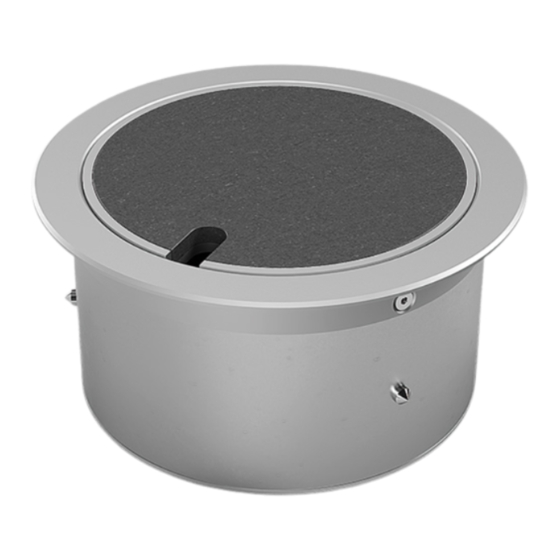
Technische Daten/Technical specifications Art.-Nr. 9901A Item No Abmessungen Ø 140 mm x 74 mm Dimensions Einbaumaße Ø 120 mm x 72 mm Instl dim 2 x hinten/back, 2 x unten/below, Zuleitungen je/each Ø 25 mm Supply line Belagsaussparung 5 mm... -
Page 5: Produktbeschreibung
Deutsch Produktbeschreibung Bezeichnung Deckel Geräteträger Rahmen/Kranz Gehäuse Gehäuseboden... -
Page 6: Montageanleitung Für Estrichböden
1. Montage im Estrich Schritt 1 Den Deckel abnehmen und den Geräteträger oder Kunststoff einführen. Nun den Platzhalter (PH) vom Gehäuse abschrauben. Die Leitungen/Leer- mit Estrich (E) eingießen. Dabei ist die spätere rohre (L) zur Einbauposition der Bodensteckdose Aufbauhöhe zu beachten. - Page 7 Schritt 2 Nach dem Aushärten des Estrichs (E) den Platz- Bodenbelag (B) verteilen. Danach die Leerohre (L) in das Gehäuse einführen und das Gehäuse im Ausschnitt halter (PH) aus dem Estrich entfernen und den platzieren. Bodenbelag (B) im Raum verlegen. Anschließend Silikon (S) rund um den Ausschnitt auf dem...
- Page 8 Schritt 3 Mit Hilfe der Madenschrauben (M) die Bodensteckdose im Estrich (E) verankern. Danach die Geräte anschließen und den Geräteträger , wieder in das Gehäuse einschrauben.
- Page 9 Schritt 4 Den Deckel mit Belag (B) ausfüllen und wieder einsetzen. Die Bodensteckdose ist nun erfolgreich eingebaut. (Siehe auch Querschnitt auf Seite 14).
-
Page 10: Montageanleitung Für Hohlböden
2. Montage im Hohlboden Schritt 1 Schritt 2 Den Deckel abmontieren und den Geräteträger An gewünschter Position einen Ausschnitt in der Größe vom Gehäuse abschrauben. der Gehäuse -Einbaumaße (!) in den Hohlboden (H) sägen/schneiden. Die Leehrohre, oder Leitungen (L) zu dieser Position verlegen. - Page 11 Schritt 3 Anschließend Silikon (S) rund um den Ausschnitt auf Nun die Bodensteckdose in den Ausschnitt absenken und auf den Rahmen aufsetzen. Das Silikon (S) dem Bodenbelag (B) verteilen. Die Leerrohre oder Leitungen (L) von unten in das Gehäuse einführen. aushärten lassen.
- Page 12 Schritt 4 Mit Hilfe der Madenschrauben (M) die Bodensteck- dose im Hohlboden (H) verankern. Danach die Geräte anschließen und den Geräteträger , wieder in das Gehäuse einschrauben.
- Page 13 Schritt 5 Den Deckel mit Belag (B) ausfüllen und wieder einsetzen. Die Bodensteckdose ist nun erfolgreich eingebaut. (Siehe auch Querschnitt auf Seite 14).
- Page 14 1. Estrichboden: Ansicht im Querschnitt, (B) Bodenbelag, (E) Estrich, (L) Leerrohre, (P) Polystyrol-Dämmschicht. 2. Hohlboden: Ansicht im Querschnitt, (B) Bodenbelag, (H) Hohlboden, (L) Leerrohre, (S) Stütze.
-
Page 15: Gebrauchshinweise
Gebrauchshinweise Um eine anhaltende Funktion der Bodensteckdose zu • Trotz Fertigungsprüfung kann es im Herstellungs- gewährleisten sind folgende Hinweise zu beachten: prozess zu scharfen Kanten oder Ecken an Gehäuse, Deckel oder anderen Bauteilen kommen. • Anschluss, Reparatur oder Instandhaltung sind von einer ausgebildeten Fachkraft durchzuführen. -
Page 16: Product Description
English Product description Designation: Lid Device Carrier Frame Housing Housing Bottom... -
Page 17: Assembly Instructions For Screed Floor
1. Installation in the screed floor Step 1 Remove the lid and unscrew the device carrier pour the placeholder (PH) with screed (E). The later from the housing . Lay the cables /conduits (L) to the construction height must be taken into account. Let the installation position of the floor socket and insert them screed (E) harden. - Page 18 Step 2 After the screed (E) has hardened, remove the place- flooring (B). Insert the cables /conduits (L) into the housing and put the floor socket into the cutout and holder (PH) from the screed and lay the floor covering place it on the frame ...
- Page 19 Step 3 Anchor the floor socket in the screed (E) with the help of the grub screws (M). Then connect the devices and screw the device carrier back into the housing .
- Page 20 Step 4 Fill the lid with floor covering (B) and reinsert. The floor socket is now successfully installed. (See also cross section on page 25).
-
Page 21: Assembly Instructions For Raised Floor
2. Installation in the raised access floor Step 1 Step 2 Remove the lid and unscrew the device Saw/cut a cut-out in the size of the housing carrier from the housing . installation dimensions (!) into the raised floor (H) at the desired position. - Page 22 Step 3 Then spread silicone (S) around the cutout on the flooring (B). Insert the conduits (L) into the housing . Now put the floor socket into the cutout and place it on the frame . Let the silicon (S) harden.
- Page 23 Step 4 Anchor the floor socket in the raised floor (H) with the help of the grub screws (M). Then connect the devices and screw the device carrier back into the housing .
- Page 24 Step 5 Fill the lid with floor covering (B) and reinsert. The floor socket is now successfully installed. (See also cross section on page 25).
- Page 25 1. Screed floor: Cross-section view, (B) flooring, (E) screed, (L) conduits, (P) polystyrene insulation layer. 2. Raised floor: Cross-section view, (B) flooring, (H) raised floor, (L) conduits, (S) pillar.
-
Page 26: Instructions For Use
Instructions for use In order to ensure a lasting function of the floor socket, • Despite manufacturing inspection, sharp edges or the following instructions must be observed: corners on housings, lids, or other components may occur during the manufacturing process. •... - Page 28 Irrtümer und technische Änderungen vorbehalten. Errors and technical changes reserved. BS Bodensteckdosen Systemtechnik GmbH Dingerdisser Str. 36 | 33699 Bielefeld | Tel +49 521 9892780 info@bodensteckdosen.com | www.bodensteckdosen.com...
Need help?
Do you have a question about the 9901A and is the answer not in the manual?
Questions and answers