Table of Contents
Advertisement
Quick Links
Advertisement
Table of Contents

Related Manuals for Kramer VDS


Summary of Contents for Kramer VDS
- Page 1 USER MANUAL MODEL: Video Display System P/N: 2900-300285 Rev 2...
-
Page 2: Table Of Contents
Figure 3: Remote Unit Figure 4: Remote Dual Screen Figure 5: Control Unit and Optional Remote Computers Figure 6: Detailed Connections Figure 7 VDS Configuration without Remote Computers Figure 8: Remote Unit Connection Figure 9: Control Unit Panel VDS – Contents... -
Page 3: Introduction
Scan Converters and Scalers; GROUP 8: Cables and Connectors; GROUP 9: Room Connectivity; GROUP 10: Accessories and Rack Adapters and GROUP 11: Sierra Products. Congratulations on purchasing your Kramer VDS Video Display System, which is ideal for the following typical applications: ... -
Page 4: Getting Started
Avoid interference from neighboring electrical appliances that may adversely influence signal quality Position your Kramer VDS away from moisture, excessive sunlight and dust This equipment is to be used only inside a building. It may only be connected to other equipment that is installed inside a building. -
Page 5: Safety Instructions
Kramer Electronics has made arrangements with the European Advanced Recycling Network (EARN) and will cover any costs of treatment, recycling and recovery of waste Kramer Electronics branded equipment on arrival at the EARN facility. For details of Kramer’s recycling arrangements in your particular country... -
Page 6: Overview
Remote units that connect to each remote monitor/computer Remote dual screen that connects two monitors to the system CAT 5 UTP or FTP cables connect the VDS system. The remote units can be up to 110m (360ft) away from the broadcaster. This table defines the models:... -
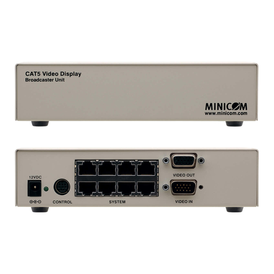
Page 7: Defining The Vds Video Display System
With both applications you can broadcast video up to resolutions of 1920x1080 @60Hz depending on the cable length. Defining the VDS Video Display System The figures below illustrate the broadcaster unit (Figure... -
Page 8: Figure 2: Line Splitter
Line Splitter Figure 2: Line Splitter (Optional) System Video Picture adjuster cable cable VIDEO IN PICTURE SYSTEM Side A Side B Monitor Figure 3: Remote Unit VDS Remote Dual Screen System cable monitors Figure 4: Remote Dual Screen VDS - Overview... -
Page 9: Expanding The Vds System
Expanding the VDS System You can expand the VDS system to 512 remote units by having two levels of line splitters. Level 1 line splitters can have eight remote units or line splitters connected. Level 2 line splitters can have eight remote units connected. -
Page 10: Connecting The Vds
Connecting the VDS Warning! In the VDS system the CAT 5 UTP or FTP cables carry electrical power. Connect them only to devices of the VDS family. Do NOT mix them with devices of other families such as AVDS. Damage will occur. -
Page 11: Figure 5: Control Unit And Optional Remote Computers
Level 1 Splitter Video cable Optional Remote Remote computer CAT5 cables to Remotes Line Level 2 Splitter Video cable CAT5 cables to Remotes Optional Remote Remote computer Figure 5: Control Unit and Optional Remote Computers VDS - Connecting the VDS... -
Page 12: Vds Detailed Connections
VDS Detailed Connections Figure 6 illustrates the detailed connections of the VDS units. Figure 6: Detailed Connections VDS - Connecting the VDS... -
Page 13: Configuring Vds Without Remote Computers
Configuring VDS without Remote Computers Figure 7 illustrates the VDS configuration without optional computers connected to the remote units and the remote dual screen. Connect the broadcaster and line splitters as illustrated in Figure Figure 6 illustrates the detailed connections of the remote unit. -
Page 14: Figure 8: Remote Unit Connection
Figure 8 illustrates the remote unit connection. CAT5 cable to Broadcaster or Line Splitter Remote PICTURE Figure 8: Remote Unit Connection VDS - Connecting the VDS... -
Page 15: Operating The Vds System
Operating the VDS system Once connected the VDS system broadcasts to all remote monitors. VDS Control Unit Figure 9 illustrates the panel of the VDS control unit. VDS Control Unit To Broadcaster Unit’s Control port Master Dark to all MINICOM... -
Page 16: Technical Specifications
118mm x 96mm x 42mm (4.6” x 3.8” x 1.7”) (line splitter); 78mm x 62mm x 23mm (3.1” x 2.4” x 0.9”) (remote) ACCESSORIES: Power supply (broadcaster, line splitter) WARRANTY: 3 years Specifications are subject to change without notice VDS - Technical Specifications... - Page 18 For the latest information on our products and a list of Kramer distributors, visit our Web site where updates to this user manual may be found. We welcome your questions, comments, and feedback. SAFETY WARNING Disconnect the unit from the power...
Need help?
Do you have a question about the VDS and is the answer not in the manual?
Questions and answers