Advertisement
Quick Links
1
Description
The DEM-OPA-SOT-1A demonstration fixture is a generic, unpopulated printed circuit board (PCB)
designed to provide an optimized layout when evaluating wideband operational amplifiers in the tiny SC70
package.
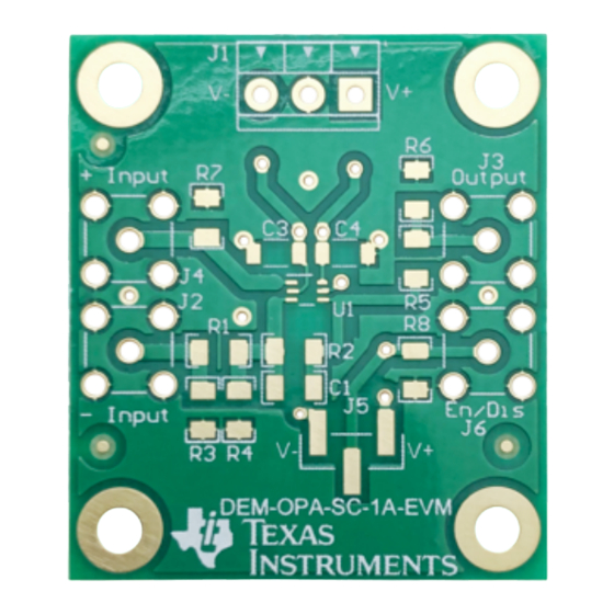
Figure 1
well as good PCB layout techniques, see the individual amplifier data sheets.
Only a few components are necessary to be assembled onto the board to set up the operational amplifier
in either an inverting or noninverting configuration. To avoid parasitic component inductance the board
only accepts surface mount resistors and capacitors. The actual values of the components, especially the
resistors, depend on the type of operational amplifier used and the intended mode of operation. The board
was designed to accommodate a variety of amplifiers: voltage feedback types or current feedback types.
The layout includes an optional function pin for those amplifiers featuring a disable function.
layer view) illustrates that the user has the option to jumper the connection to the positive or negative
supply, or connect it to an external SMA connector.
For a detailed discussion on the individual op amp and the appropriate selection of the recommended
feedback and gain resistors, see the respective data sheets. As a reminder, the frequency response
performance of a current feedback amplifier is determined by the feedback resistor value. Also note that
the feedback resistor compensates for the package parasitics, and therefore its value usually varies for
different packages.
SBOU232 – October 2019
Submit Documentation Feedback
DEM-OPA-SC-1A-EVM Evaluation Module
shows the package pinout for this PCB. For more information on these op amps, as
Copyright © 2019, Texas Instruments Incorporated
User's Guide
SBOU232 – October 2019
DEM-OPA-SC-1A-EVM Evaluation Module
Figure 4
(top
1
Advertisement

Related Manuals for Texas Instruments DEM-OPA-SC-1A-EVM


Summary of Contents for Texas Instruments DEM-OPA-SC-1A-EVM
- Page 1 Also note that the feedback resistor compensates for the package parasitics, and therefore its value usually varies for different packages. SBOU232 – October 2019 DEM-OPA-SC-1A-EVM Evaluation Module Submit Documentation Feedback Copyright © 2019, Texas Instruments Incorporated...
- Page 2 Any larger transient currents will have a short loop, and will not reflect to the input and cause an increase in distortion. 2.2 F 0.1 F 0.1 F 2.2 F 49.9W 49.9W Enable/ Disable 49.9W (Optional) Figure 2. DEM-OPA-SC-1A Schematic DEM-OPA-SC-1A-EVM Evaluation Module SBOU232 – October 2019 Submit Documentation Feedback Copyright © 2019, Texas Instruments Incorporated...
-
Page 3: Board Layout
Figure 3. DEM-OPA-SC-1A Top Silkscreen Figure 4. DEM-OPA-SC-1A Top Layer Figure 5. DEM-OPA-SC-1A Bottom Layer Figure 6. DEM-OPA-SC-1A Bottom Silkscreen SBOU232 – October 2019 DEM-OPA-SC-1A-EVM Evaluation Module Submit Documentation Feedback Copyright © 2019, Texas Instruments Incorporated... -
Page 4: Measurement Tips
If a high-impedance probe must be used, place a 100-Ω resistor on the probe tip to isolate its capacitance from the circuit. DEM-OPA-SC-1A-EVM Evaluation Module SBOU232 – October 2019 Submit Documentation Feedback Copyright © 2019, Texas Instruments Incorporated... - Page 5 STANDARD TERMS FOR EVALUATION MODULES Delivery: TI delivers TI evaluation boards, kits, or modules, including any accompanying demonstration software, components, and/or documentation which may be provided together or separately (collectively, an “EVM” or “EVMs”) to the User (“User”) in accordance with the terms set forth herein.
- Page 6 www.ti.com Regulatory Notices: 3.1 United States 3.1.1 Notice applicable to EVMs not FCC-Approved: FCC NOTICE: This kit is designed to allow product developers to evaluate electronic components, circuitry, or software associated with the kit to determine whether to incorporate such items in a finished product and software developers to write software applications for use with the end product.
- Page 7 www.ti.com Concernant les EVMs avec antennes détachables Conformément à la réglementation d'Industrie Canada, le présent émetteur radio peut fonctionner avec une antenne d'un type et d'un gain maximal (ou inférieur) approuvé pour l'émetteur par Industrie Canada. Dans le but de réduire les risques de brouillage radioélectrique à...
- Page 8 www.ti.com EVM Use Restrictions and Warnings: 4.1 EVMS ARE NOT FOR USE IN FUNCTIONAL SAFETY AND/OR SAFETY CRITICAL EVALUATIONS, INCLUDING BUT NOT LIMITED TO EVALUATIONS OF LIFE SUPPORT APPLICATIONS. 4.2 User must read and apply the user guide and other available documentation provided by TI regarding the EVM prior to handling or using the EVM, including without limitation any warning or restriction notices.
- Page 9 Notwithstanding the foregoing, any judgment may be enforced in any United States or foreign court, and TI may seek injunctive relief in any United States or foreign court. Mailing Address: Texas Instruments, Post Office Box 655303, Dallas, Texas 75265 Copyright © 2019, Texas Instruments Incorporated...
- Page 10 TI products. TI’s provision of these resources does not expand or otherwise alter TI’s applicable warranties or warranty disclaimers for TI products. Mailing Address: Texas Instruments, Post Office Box 655303, Dallas, Texas 75265 Copyright © 2019, Texas Instruments Incorporated...
Need help?
Do you have a question about the DEM-OPA-SC-1A-EVM and is the answer not in the manual?
Questions and answers