
Related Manuals for Supermicro SUPERO SC847DJ Series


Summary of Contents for Supermicro SUPERO SC847DJ Series
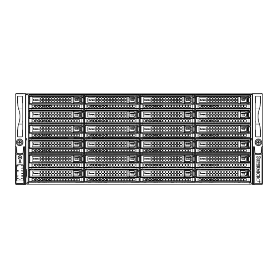
- Page 1 UPER ® DOUBLE-SIDED STORAGE SC847DJ CHASSIS SERIES SC847DE16-R2K02JBOD SC847DE26-R2K02JBOD USER’S MANUAL...
- Page 2 This product, including software and documentation, is the property of Supermicro and/or its licensors, and is supplied only under a license. Any use or reproduction of this product is not allowed, except as expressly permitted by the terms of said license.
- Page 3 Preface Preface About This Manual This manual is written for professional system integrators and PC technicians. It provides information for the installation and use of the SC847DJ chassis. Installation and maintenance should be performed by experienced technicians only. This manual lists compatible parts available when this document was published. Always refer to the our website for updates on supported parts and configurations.
- Page 4 Not all compatible backplanes are listed. Refer to our website for the latest compatible backplane information. Appendix A Hardware This section provides information on cabling, and other hardware which is compat- ible with your chassis. For complete information on supported cables and hardware, refer to the Supermico website at www.supermicro.com.
- Page 5 Appendix C BPN-SAS2-847DF Front Backplane Specifications This section contains detailed specifications on the BPN-SAS2-847DF front back- plane. Additional information can be found on the Supermicro website at www. supermicro.com. Appendix D BPN-SAS2-847DJ Rear Backplane Specifications This chapter contains information on the BPN-SAS2-847DJ rear backplane. Addi- tional information can be found on the Supermicro website at www.supermicro.com.
-
Page 6: Table Of Contents
Chapter 1 Introduction Overview ......................1-1 Shipping List ....................1-1 Where to get Replacement Components ............1-2 Contacting Supermicro ..................1-3 Returning Merchandise for Service..............1-4 Chapter 2 Standardized Warning Statements for AC Systems About Standardized Warning Statements ............2-1 Warning Definition ................... - Page 7 Preface Removing the Two Chassis Covers ..............4-3 Main Chassis Cover ..................4-3 Power Supply Cover ..................4-4 Installing Hot-Swappable 3.5" Hard Drives ............. 4-5 Assembling the JBOD Compartment Bracket ..........4-8 Removing and Installing Backplane Assemblies .......... 4-10 Front Backplane Removal and Installation ............4-11 Rear Backplane Removal and Installation ............
- Page 8 SC847DJ Chassis Manual Notes viii...
-
Page 9: Chapter 1 Introduction
SC847DJ is a reliable and hassle-free main- tenance storage system. Shipping List Please visit the Supermicro website for the latest shiping lists and part numbers for your particular chassis model at www.supermicro.com. SC847DJ Chassis Power... -
Page 10: Where To Get Replacement Components
Supermicro Authorized Distributors/System Integrators/Resellers. A list of Supermicro Authorized Distributors/System Integra- tors/Resellers can be found at: www.supermicro.com. Click the Where to Buy link. -
Page 11: Contacting Supermicro
Super Micro Computer, Inc. 980 Rock Ave. San Jose, CA 95131 U.S.A. Tel: +1 (408) 503-8000 Fax: +1 (408) 503-8008 Email: marketing@supermicro.com (General Information) support@supermicro.com (Technical Support) Website: www.supermicro.com Europe Address: Super Micro Computer B.V. Het Sterrenbeeld 28, 5215 ML... -
Page 12: Returning Merchandise For Service
For faster service, RMA authorizations may be requested online (http://www. supermicro.com/support/rma/). Whenever possible, repack the chassis in the original Supermicro carton, using the original packaging material. If these are no longer available, be sure to pack the chassis securely, using packaging material to surround the chassis so that it does not shift within the carton and become damaged during shipping. -
Page 13: Chapter 2 Standardized Warning Statements For Ac Systems
Only certified technicians should attempt to install or configure components. Read this appendix in its entirety before installing or configuring components in the Supermicro chassis. These warnings may also be found on our web site at http://www.supermicro.com/ about/policies/safety_information.cfm. Warning Definition Warning! This warning symbol means danger. - Page 14 SC847DJ Chassis User's Manual Warnung WICHTIGE SICHERHEITSHINWEISE Dieses Warnsymbol bedeutet Gefahr. Sie befinden sich in einer Situation, die zu Verletzungen führen kann. Machen Sie sich vor der Arbeit mit Geräten mit den Gefahren elektrischer Schaltungen und den üblichen Verfahren zur Vorbeugung vor Unfällen vertraut.
- Page 15 Warning Statements for AC Systems جسذٌة اصابة ًتتسبب ف حالة ٌوكي أى ًاًك ف خطز ًٌٌع هذا الزهز !تحذٌز الذوائز بالوخاطز الٌاجوة عي ي على علن ، ك هعذات تعول على أي قبل أى الكهزبائٍة حىادث أي وقىع وٌع ل الىقائٍة...
-
Page 16: Installation Instructions
SC847DJ Chassis User's Manual Installation Instructions Warning! Read the installation instructions before connecting the system to the power source. 設置手順書 システムを電源に接続する前に、 設置手順書をお読み下さい。 警告 将此系统连接电源前,请先阅读安装说明。 警告 將系統與電源連接前,請先閱讀安裝說明。 Warnung Vor dem Anschließen des Systems an die Stromquelle die Installationsanweisungen lesen. ¡Advertencia! Lea las instrucciones de instalación antes de conectar el sistema a la red de alimentación. -
Page 17: Circuit Breaker
Chapter 2: Warning Statements for AC Systems Circuit Breaker Warning! This product relies on the building's installation for short-circuit (overcurrent) protection. Ensure that the protective device is rated not greater than: 250 V, 20 A. サーキッ ト ・ ブレーカー この製品は、 短絡 (過電流) 保護装置がある建物での設置を前提としています。 保護装置の定格が250 V、... -
Page 18: Power Disconnection Warning
SC847DJ Chassis User's Manual 경고! 이 제품은 전원의 단락(과전류)방지에 대해서 전적으로 건물의 관련 설비에 의존합니다. 보호장치의 정격이 반드시 250V(볼트), 20A(암페어)를 초과하지 않도록 해야 합니다. Waarschuwing Dit product is afhankelijk van de kortsluitbeveiliging (overspanning) van uw electrische installatie. Controleer of het beveiligde aparaat niet groter gedimensioneerd is dan 220V, 20A. - Page 19 Chapter 2: Warning Statements for AC Systems ¡Advertencia! El sistema debe ser disconnected de todas las fuentes de energía y del cable eléctrico quitado de los módulos de fuente de alimentación antes de tener acceso el interior del chasis para instalar o para quitar componentes de sistema. Attention Le système doit être débranché...
-
Page 20: Equipment Installation
SC847DJ Chassis User's Manual Equipment Installation Warning! Only trained and qualified personnel should be allowed to install, replace, or service this equipment. 機器の設置 トレーニングを受け認定された人だけがこの装置の設置、 交換、 またはサービスを許可 されています。 警告 只有经过培训且具有资格的人员才能进行此设备的安装、更换和维修。 警告 只有經過受訓且具資格人員才可安裝、更換與維修此設備。 Warnung Das Installieren, Ersetzen oder Bedienen dieser Ausrüstung sollte nur geschultem, qualifiziertem Personal gestattet werden. -
Page 21: Restricted Area
Chapter 2: Warning Statements for AC Systems Waarschuwing Deze apparatuur mag alleen worden geïnstalleerd, vervangen of hersteld door geschoold en gekwalificeerd personeel. Restricted Area Warning! This unit is intended for installation in restricted access areas. A restricted access area can be accessed only through the use of a special tool, lock and key, or other means of security. -
Page 22: Battery Handling
SC847DJ Chassis User's Manual אזור עם גישה מוגבלת !אזהרה יש להתקין את היחידה באזורים שיש בהם הגבלת גישה. הגישה ניתנת בעזרת .)'כלי אבטחה בלבד (מפתח, מנעול וכד محظورة مناطق ٍنتركُبها ف هذه انىحذة تخصيص تم ،أداة خاصت من خالل استخذاو فقط... - Page 23 Chapter 2: Warning Statements for AC Systems Warnung Bei Einsetzen einer falschen Batterie besteht Explosionsgefahr. Ersetzen Sie die Batterie nur durch den gleichen oder vom Hersteller empfohlenen Batterietyp. Entsorgen Sie die benutzten Batterien nach den Anweisungen des Herstellers. Attention Danger d'explosion si la pile n'est pas remplacée correctement. Ne la remplacer que par une pile de type semblable ou équivalent, recommandée par le fabricant.
-
Page 24: Redundant Power Supplies
SC847DJ Chassis User's Manual Redundant Power Supplies Warning! This unit might have more than one power supply connection. All connections must be removed to de-energize the unit. 冗長電源装置 このユニッ トは複数の電源装置が接続されている場合があります。 ユニッ トの電源を切るためには、 すべての接続を取り外さなければなりません。 警告 此部件连接的电源可能不止一个,必须将所有电源断开才能停止给该部件供电。 警告 此裝置連接的電源可能不只一個,必須切斷所有電源才能停止對該裝置的供電。 Warnung Dieses Gerät kann mehr als eine Stromzufuhr haben. Um sicherzustellen, dass der Einheit kein trom zugeführt wird, müssen alle Verbindungen entfernt werden. -
Page 25: Backplane Voltage
Chapter 2: Warning Statements for AC Systems امداد الطاقة بوحدات عدة اتصاالت جهاز ال يكون لهذا قد الكهرباء عن وحدة ال لعسل كافة االتصاالت يجب إزالة 경고! 이 장치에는 한 개 이상의 전원 공급 단자가 연결되어 있을 수 있습니다. 이 장치에 전원을... -
Page 26: Comply With Local And National Electrical Codes
SC847DJ Chassis User's Manual מתח בפנל האחורי !הרה אז קיימת סכנת מתח בפנל האחורי בזמן תפעול המערכת. יש להיזהר במהלך .העבודה اللىحة أوالطاقة المىجىدة على التيار الكهزبائي مه خطز هناك هذا الجهاس خدمة كه حذرا عند يعمل النظام عندما يكىن 경고! 시스템이... -
Page 27: Product Disposal
Chapter 2: Warning Statements for AC Systems Attention L'équipement doit être installé conformément aux normes électriques nationales et locales. תיאום חוקי החשמל הארצי !אזהרה הציוד חייבת להיות תואמת לחוקי החשמל המקומיים והארציים התקנת المتعلقة المحلية والىطىية قىاويه يجب أن يمتثل لل الكهربائية... -
Page 28: Hot Swap Fan Warning
SC847DJ Chassis User's Manual ¡Advertencia! Al deshacerse por completo de este producto debe seguir todas las leyes y reglamentos nacionales. Attention La mise au rebut ou le recyclage de ce produit sont généralement soumis à des lois et/ou directives de respect de l'environnement. Renseignez-vous auprès de l'organisme compétent. - Page 29 Chapter 2: Warning Statements for AC Systems 警告 當您從機架移除風扇裝置,風扇可能仍在轉動。小心不要將手指、螺絲起子和其他 物品太靠近風扇。 Warnung Die Lüfter drehen sich u. U. noch, wenn die Lüfterbaugruppe aus dem Chassis genommen wird. Halten Sie Finger, Schraubendreher und andere Gegenstände von den Öffnungen des Lüftergehäuses entfernt. ¡Advertencia! Los ventiladores podran dar vuelta cuando usted quite ell montaje del ventilador del chasis.
-
Page 30: Power Cable And Ac Adapter
Electrical Appliance and Material Safety Law prohibits the use of UL or CSA -certified cables (that have UL/CSA shown on the code) for any other electrical devices than products designated by Supermicro only. 電源コードとACアダプター 製品を設置する場合、 提供または指定された接続ケーブル、 電源コードとACアダプター... - Page 31 Appareils électroménagers et de loi sur la sécurité Matériel interdit l'utilisation de UL ou CSA câbles certifiés qui ont UL ou CSA indiqué sur le code pour tous les autres appareils électriques que les produits désignés par Supermicro seulement.
- Page 32 SC847DJ Chassis User's Manual Notes 2-20...
-
Page 33: Chapter 3 System Interface
Chapter 3 System Interface Chapter 3 System Interface Overview There are several LEDs on the control panel as well as others on the drive carriers to keep you constantly informed of the overall status of the system as well as the activity and health of specific components. -
Page 34: Control Panel Buttons
SC847DJ Chassis Manual Control Panel Buttons There are two push-buttons located on the left handle of the chassis. These are (in order from top to bottom) a power on/off button and a reset button. Power: The main power button is used to apply or remove power from the power supply to the server system. - Page 35 Chapter 3 System Interface NIC1: Indicates network activity on GLAN1 when flashing. Information LED: Informational LED Status Description An overheat condition has occured. Solid red (This may be caused by cable congestion). Fan failure, check for an inoperative fan. Blinking red (1Hz) Power failure, check for a non-operational Blinking red (0.25Hz) power supply.
-
Page 36: Drive Carrier Leds
SC847DJ Chassis Manual Drive Carrier LEDs The SC847DJ chassis uses SAS or SATA drives. SAS/SATA Drives Each SAS/SATA drive carrier has two sets of LEDs, one set of blue and red LED indicators for each drive. These LEDs are distinguished with a letter F indicator for front drives and a letter R indicator for rear drives on the drive carrier bezel. - Page 37 Chapter 5 Cascading Configurations Chapter 5 Cascading Configurations Cascading Configuration Overview The SC847DJ chassis backplanes can be configured in a variety of combinations for different applications. The following sections will provide cascading configuration options specific to your system. Single Node, Single Host Cascading The following configuration demonstrates cascading in a single node, single host system.
- Page 38 SC847DJ Chassis Manual Two Node Cluster Failover Configuration Option 1 The following configuration option demonstrates cascading with a two node cluster, which provides high performance, availability and redundancy. Front Expander Host 1 Host 2 Primary 9207-8e 9207-8e Secondary 9207-8e 9207-8e PRESS FIT PRESS FIT PRESS FIT...
- Page 39 Chapter 5 Cascading Configurations Two Node Cluster Failover Configuration Option 2 The following configuration option demonstrates cascading with a two node cluster, which provides high performance, availability and redundancy. Front Expander Primary Secondary Host 1 Host 2 PRESS FIT PRESS FIT PRESS FIT PRESS FIT PRESS FIT...
- Page 40 SC847DJ Chassis Manual Notes...
-
Page 41: Chapter 4 Chassis Setup And Maintenance
Chapter 4 Chassis Setup and Maintenance Chapter 4 Chassis Setup and Maintenance Overview This chapter covers the steps required to install components and perform mainte- nance on the chassis. The only tool you will need to install components and perform maintenance is a Phillips screwdriver. -
Page 42: Powering Up And Shutting Down The System
SC847DJ Chassis Manual Powering Up and Shutting Down the System The procedures for powering up and shutting down the SC847DJ differ slightly from typical systems. It is important to become familiar with the procedure and to follow it each time that the system is powered up or shut down. Powering Up the System First Time or Power Loss Power Up Procedure If powering up your system for the first time or after a loss of power, wait until the... -
Page 43: Removing The Two Chassis Covers
Chapter 4 Chassis Setup and Maintenance Removing the Two Chassis Covers Remove Five Screws Figure 4-1. Removing the Main Chassis Cover Main Chassis Cover Removing Main Chassis Cover 1. Power down the system as described on page 4-2 and unplug the power cords from the rear of the power supplies. -
Page 44: Power Supply Cover
SC847DJ Chassis Manual Figure 4-2. Removing the Power Supply Cover Power Supply Cover Removing Power Supply Cover 1. Power down the system as described on page 4-2 and unplug the power cords from the rear of the power supplies. 2. Remove the four screws securing the power supply cover. 3. -
Page 45: Installing Hot-Swappable 3.5" Hard Drives
Chapter 4 Chassis Setup and Maintenance Installing Hot-Swappable 3.5" Hard Drives Figure 4-2. Removing a 3.5" Hard Drive Carrier The SC847DJ chassis supports ninety 3.5" hard drives in forty-five hot-swappable double-depth HDD bays. There are twenty-four hard drive bays in the front of the chassis and twenty-one in the rear. - Page 46 5. Secure the hard drive to the carrier using six screws. 6. Repeat steps 3 through 5 for the second of the two hard drives. Warning! Enterprise level hard disk drives are recommended for use in Supermicro chassis and servers. For information on recommended HDDs, visit the Supermicro...
- Page 47 Chapter 4 Chassis Setup and Maintenance 7. Return the hard drive carrier to the hard drive bay in the chassis. Make sure to close the drive carrier handle to lock the drive carrier into place. Figure 4-5. Installing the Hard Drives and Carrier into the Chassis...
-
Page 48: Assembling The Jbod Compartment Bracket
SC847DJ Chassis Manual Assembling the JBOD Compartment Bracket Figure 4-6. Removing the Dummy Bracket The SC847DJ chassis includes a JBOD compartment bracket, which holds the CSE-PTJBOD-CB3, two or four MCP-280-84701-0N Mini SAS HD converters and one CBL-NTWK-0584 IPMI LAN port extension cable. Assembling the Components of the JBOD Compartment Bracket 1. - Page 49 Chapter 4 Chassis Setup and Maintenance 6. Align the four Mini SAS adapters with the JBOD compartment bracket. 7. Secure the IPMI LAN port extension cable connector into the four Mini SAS HD converters and secure it to the plastic holder with three screw. 8.
-
Page 50: Removing And Installing Backplane Assemblies
SC847DJ Chassis Manual Removing and Installing Backplane Assemblies The SC847DJ includes two backplane assemblies which consist of front and rear backplanes contained in brackets, fitted with expander boards. The front backplane assembly is located directly in front of the fan bracket at the front of the chassis. The rear backplane assembly is located behind the fan bracket. -
Page 51: Front Backplane Removal And Installation
Chapter 4 Chassis Setup and Maintenance Front Backplane Removal and Installation Removing and Installing the Front Backplane Assembly 1. Power down the system as described on page 4-2, unplug the power cords from the rear of the power supplies and remove the chassis main cover as described on page 4-3. - Page 52 SC847DJ Chassis Manual 8. Insert the replacement front expander board into the backplane. 9. Place the replacement front backplane in the front backplane bracket and secure the two halves of the bracket together with the ten screws previously set aside. 10.
-
Page 53: Rear Backplane Removal And Installation
Chapter 4 Chassis Setup and Maintenance Rear Backplane Removal and Installation Remove the four upper screws along the top and two lower screws along the bottom of the rear backplane bracket Remove the eight lower screws that secure the expander board to the floor of the chassis. - Page 54 SC847DJ Chassis Manual Figure 4-14. Installing the Rear Backplane Assembly 7. Separate the two halves of the backplane bracket from each other and lift the rear backplane out of its bracket. 8. Carefully pull the rear expander board out of its slot in the backplane. 9.
-
Page 55: Installing The Air Shroud
Chapter 4 Chassis Setup and Maintenance Installing the Air Shroud Figure 4-15. Installing the Air Shroud Air shrouds concentrate airflow to maximize fan efficiency. The SC847DJ uses an air shroud to optimize cooling within the chassis. Installing the Air Shroud 1. -
Page 56: Checking The Server's Airflow
SC847DJ Chassis Manual Checking the Server's Airflow Checking the Airflow 1. Make sure there are no objects to obstruct airflow in and out of the server. In addition, if you are using a front bezel, make sure the bezel's filter is replaced periodically. -
Page 57: System Fans
Chapter 4 Chassis Setup and Maintenance System Fans Seven hot-swappable, heavy-duty fans provide cooling for the chassis. These fans circulate air through the chassis thereby lowering the chassis internal temperature. The SC847DJ chassis is designed with the option to remove individual fans or to remove the entire fan housing. - Page 58 SC847DJ Chassis Manual Removing the Fan Housing (Optional Method) 1. Remove the main chassis cover as described on page 4-3 while the power is running to determine which fan has failed. Never run the server for an extended period of time with the chassis top covers off. 2.
- Page 59 Chapter 4 Chassis Setup and Maintenance 9. Return the fan housing to its original position in the chassis and secure it with the two side screws previously set aside. 10. Reconnect the wiring to the fan. 11. Replace the main chassis cover as described on page 4-3, reconnect the power cords to the rear of the power supplies and power up the system as described on page 4-2.
-
Page 60: 4-10 Power Supply
Redundant power supplies are hot-swappable, and can be changed without pow- ering down the system. New units can be ordered directly from Supermicro (see contact information in the Preface). Release Figure 4-20. -
Page 61: 4-11 Replacing The Power Distributor
Chapter 4 Chassis Setup and Maintenance 4-11 Replacing the Power Distributor The SC847DJ chassis comes equipped with a power distributor. In the unlikely event that you need to replace the power distributor, use the following instructions. Changing the Power Distributor 1. - Page 62 SC847DJ Chassis Manual Notes 4-22...
- Page 63 This appendix lists supported cables for your chassis system. It only includes the most commonly used components and configurations. For more compatible cables, refer to the manufacturer of the motherboard you are using and our Web site at: www.supermicro.com. A-2 Cables Included with SC847DJ Chassis (SAS/SATA) SC847DJ...
- Page 64 SC847DJ Chassis Manual A-4 Chassis Screws The accessory box includes all the screws needed to set up your chassis. This section lists and describes the most common screws used. Your chassis may not require all the parts listed. HARD DRIVE Flat head Pan head 6-32 x 5 mm...
- Page 65 Appendix B Power Supply Specifications Appendix B SC847DJ Power Supply Specifications This appendix lists power supply specifications for your chassis system. SC847DJ 2000W MFR Part # PWS-2K02P-1R 1100W Output @ 100-120V, 12.7-10.5A, 50-60Hz 1400W Output @ 120-140V, 13.5-11.5A, 50-60Hz 1800W Output @ 200-220V, 10.0-9.5A, 50-60Hz AC Input 1980W Output @ 220-230V, 10.0-9.8A, 50-60Hz 2000W Output @ 230-240V, 10.0-9.8A, 50-60Hz...
- Page 66 SC847DJ Chassis Manual Notes...
- Page 67 Appendix C BPN-SAS2-847DF Backplane Specifications Appendix C BPN-SAS2-847DF Backplane Specifications To avoid personal injury and property damage, carefully follow all the safety steps listed below when accessing your system or handling the components. C-1 ESD Safety Guidelines Electrostatic Discharge (ESD) can damage electronic com ponents. To prevent dam- age to your system, it is important to handle it very carefully.
- Page 68 This manual reflects BPN-SAS2-847DF Revision 1.02, BPN-EXP-847DF3EL1 Revi- sion 1.02 and MCP-280-00024-0N Revision 1.02, the most current releases avail- able at the time of publication. Always refer to the Supermicro website at www.su- permicro.com for the latest updates, compatible parts and supported configurations.
- Page 69 Appendix C BPN-SAS2-847DF Backplane Specifications C-5 Overview of the SC847DJ Chassis Configuration The SC847DJ chassis configuration consists of the following components: One BPN-SAS2-847DF front backplane, one BPN-SAS2-847DJ rear backplane, one or two BPN-EXP-847DF3EL1 expander card(s) on the front backplane, one or two BPN-EXP-847DF3EL1 expander card(s) on the rear backplane, and a total of thirty-six MCP-280-00024-0N adapter cards in double-depth hard drive carriers.
- Page 70 SC847DJ Chassis Manual C-6 BPN-SAS2-847DF Backplane Front Connectors BPN-SAS2-847DF REV:1.02 U202 EC18 DESIGNED IN USA EC23 EC19 EC20 EC24 EC26 BAR CODE EC28 EC22 U207 U211 EC27 BC40 EC11 EC25 EC10 BC39 EC12 U208 EC29 EC13 U209 U212 EC39 U213 EC30 EC15 EC32...
- Page 71 Appendix C BPN-SAS2-847DF Backplane Specifications 1. - 3. Power Connectors These connectors, designated JPW1, JPW2. JPW3, JPW4 and JPW5 supply power to the chassis. 4. Primary Expander Power Connector Supplies power to the primary expander board. This connector is designated J26. 5.
- Page 72 SC847DJ Chassis Manual C-7 BPN-SAS2-847DF Rear SAS2 Receptacles SAS #0,#1 #2,#3 #4,#5 #6,#7 S8 E16 #8,#9 #10,#11 #12,#13 #14,#15 #16,#17 #18,#19 #20,#21 #22,#23 #24,#25 #26,#27 #28,#29 #30,#31 #30 #31 S8 E16 C111 C126 C127 C237 U219 R161 #32,#33 #34,#35 #36,#37 #38,#39 R353 C402...
- Page 73 Appendix D BPN-SAS2-847DJ Appendix D BPN-SAS2-847DJ Backplane Specifications D-1 Chassis Configuration The SC847DJ chassis configuration consists of the following components: • One front backplane, BPN-SAS2-847DF • One rear backplane, BPN-SAS2-847DJ • One or two rear expander cards, BPN-EXP-847DF3EL1 on each backplane •...
- Page 74 1.02, BPN-EXP-847DF3EL1 Revision 1.02 and MCP-280-00024-0N Revision 1.02, the most current releases available at the time of publication. Always refer to the Supermicro web site at www.supermicro.com for the latest updates, compatible parts and supported configurations. All images and layouts shown in this user's guide are based upon the latest PCB revision available at the time of publishing.
- Page 75 Appendix D BPN-SAS2-847DJ To avoid personal injury and property damage, carefully follow all the safety steps listed below when accessing your system or handling the components. D-3 ESD Safety Guidelines Electrostatic Discharge (ESD) can damage electronic com ponents. To prevent dam- age to your system, it is important to handle it very carefully.
- Page 76 Appendix D BPN-SAS2-847DJ D-5 BPN-SAS2-847DJ Backplane Front Connectors U203 BPN-SAS2-847DJ DESIGNED IN USA R219 U201 REV:1.00 R217 U202 R218 EC23 EC19 EC20 U206 R312 EC26 EC24 BAR CODE U207 U205 EC28 C224 U209 C207 EC27 U211 EC12 EC13 EC32 EC29 EC11 U212 C210...
- Page 77 SC847DJ Chassis Manual 1. - 3. Power Connectors These connectors, designated JPW1, JPW2 and JPW3 supply power to the chassis. 4. Primary Expander Power Connector Supplies power to the primary expander board. This connector is designated J26. 5. Primary Airmax Connectors These connectors are SAS2 signal connectors that connect the backplane and the primary expander board.
- Page 78 Appendix D BPN-SAS2-847DJ Rear SAS2 Receptacles #2,#3 #4,#5 #6,#7 #12,#13 #14,#15 #10,#11 #20,#21 #22,#23 #18,#19 #24, #25 #26,#27 #28,#29 #30,#31 #30 #31 U219 #32, #33 #34,#35 #36,#37 #38,#39 #40, #41 #42,#43 #44,#45 #46,#47 U221 Figure D-4. BPN-SAS2-847DJ Rear SAS2 Receptacles Rear SAS2 Receptacles Rear Receptacle SAS Drive Number...
- Page 79 SC847DJ Chassis Manual Notes...
- Page 80 Appendix E: BPN-EXP-847DF3EL1 Backplane Specifications Appendix E BPN-EXP-847DF3EL1 Backplane Specifications To avoid personal injury and property damage, carefully follow all the safety steps listed below when accessing your system or handling the components. ESD Safety Guidelines Electrostatic Discharge (ESD) can damage electronic com ponents. To prevent dam- age to your system, it is important to handle it very carefully.
- Page 81 This manual reflects BPN-SAS2-847DF Revision 1.02, BPN-EXP-847DF3EL1 Revi- sion 1.02 and MCP-280-00024-0N Revision 1.02, the most current releases avail- able at the time of publication. Always refer to the Supermicro website at www.su- permicro.com for the latest updates, compatible parts and supported configurations.
- Page 82 Appendix E: BPN-EXP-847DF1EL1 Backplane Specifications Overview of the SC847DJ Chassis Configuration The BPN-SAS2-847DF backplane configuration consists of the following components: One BPN-EXP-847DF backplane, one or two BPN-EXP-847DF3EL1 expander board, twenty-four MCP-280-00024-0N adapter cards in double-depth hard drive carriers, and one optional BPN-847DF3EL1 secondary expander board. Refer to Chapter 4 of this manual for removal and installation instructions.
- Page 83 SC847DJ Chassis Manual BPN-EXP-847DF3EL1 Expander Boards The BPN-EXP-847DF3EL1 expander boards plug into the BPN-SAS2-847DF2EL1 backplane. One or two expander boards may be used. PRESS FIT PRESS FIT PRESS FIT PRESS FIT PRESS FIT PRESS FIT PRESS FIT PRESS FIT PRESS FIT BPN-EXP-847DF3EL1 REV:1.02 PRESS FIT...
- Page 84 Appendix E: BPN-EXP-847DF1EL1 Backplane Specifications PRESS FIT PRESS FIT PRESS FIT PRESS FIT PRESS FIT PRESS FIT PRESS FIT PRESS FIT PRESS FIT BPN-EXP-847DF3EL1 REV:1.02 PRESS FIT BAR CODE U399 CA315 EXPDBG3 MAC CODE JP69 SAS CODE DESIGNED IN USA EXPDBG1 C210 EXPDBG1...
- Page 85 SC847DJ Chassis Manual Notes...
- Page 86 Appendix D CSE-PTJBOD-CB3 Power Card Specifications Appendix F CSE-PTJBOD-CB3 Power Card Specifications To avoid personal injury and property damage, carefully follow all the safety steps listed below when accessing your system or handling the components. ESD Safety Guidelines Electrostatic Discharge (ESD) can damage electronic com ponents. To prevent damage to your system, it is important to handle the backplane very carefully.
- Page 87 This manual reflects the CSE-PTJBOD-CB3 Revision 1.02 power board, the most current release available at the time of publication. Always refer to the Supermicro web site at www.supermicro.com for the latest updates, compatible parts and sup- ported configurations.
- Page 88 Appendix D CSE-PTJBOD-CB3 Power Card Specifications Components and Connectors FAN4 FAN2 FAN3 FAN5 FAN6 FAN10 FAN9 JPW1 1-2:SAS3 2-3:SAS2_847D NMI X PWR LED X NIC1 X OH/FF X RST ON PWR ON Figure F-1. Components and Connectors on the CSE-PTJBOD-CB3 Components and Connectors 1.
- Page 89 SAS2/SAS3 backplanes. 3. Manufacturing Test Connector This connector is designated J3 and is for Supermicro manufacturing use only. 4. Manufacturer's USB Test Connector This connector is designated FB1 and is for Supermicro manufacturing use only.
- Page 90 Appendix D CSE-PTJBOD-CB3 Power Card Specifications 6. IPMI LAN Connector The Intelligent Platform Management Inter- face (IPMI) LAN connector is designated J8 and supports connectivity with a local network using cable CBL-NTWK-0584 or CBL-NTWK-0587. 7. SC847D SAS2 I C Connectors The backplane connectors are designated J4-J7 and allow the power board to be con- nected to up to four SC847D expanders.
- Page 91 SC847DJ Chassis Manual Connectors Jumpers and LED Indicators SAS2/SAS3: Use JP1-JP4 FAN4 FAN2 FAN3 FAN5 FAN6 FAN10 FAN9 JPW1 1-2:SAS3 2-3:SAS2_847D NMI X PWR LED X NIC1 X OH/FF X RST ON PWR ON SC847D: Use J4-J7 Figure F-2. CSE-PTJBOD-CB3 Connectors and Jumpers Front SAS2/SAS3 and SC847D Jumpers Jumper Description...
- Page 92 Appendix D CSE-PTJBOD-CB3 Power Card Specifications FAN2 FAN4 FAN5 FAN6 FAN3 FAN10 FAN9 JPW1 1-2:SAS3 2-3:SAS2_847D NMI X PWR LED X NIC1 X OH/FF X RST ON PWR ON Figure F-3. CSE-PTJBOD-CB3 LED Indicators LED Indicators Description Heartbeat LED: A blinking LED indicates BMC activity Power LED: DC power indicator...
- Page 93 SC847DJ Chassis Manual SC847D JBOD Cabling E16 I C Cabling Use the following diagram to connect the CSE-PTJBOD-CB3 to the front and rear backplanes in SC847D JBOD E16 model chassis. Jumper Settings Jumper Setting Pins 1-2: SAS3 enabled Pins 2-3: SAS2 enabled and SC847 When enabling SAS2/SAS3 functionality, use connectors JP1-JP4, (see Page 2-4) and set the JP5 jumper to pins 1-2 (SAS3) or pins 3-4 (SAS2).
- Page 94 Appendix D CSE-PTJBOD-CB3 Power Card Specifications E26 I C Cabling Use the following diagram to connect the CSE-PTJBOD-CB3 to the front and rear backplanes in SC847D-JBOD-E26 model chassis. Front Secondary Expander Front Primary Expander BPN-EXP-847DF3EL1 BPN-EXP-847DF3EL1 CBL-0157L CBL-0157L-01 CBL-0157L-01 CBL-0157L-01 CSE-PTJBOD-CB3 Rear Primary Expander Rear Secondary Expander...
- Page 95 SC847DJ Chassis Manual SC847 JBOD Cabling SAS3 I C Cabling in the SC847 JBOD Chassis Use the diagram below to connect the CSE-PTJBOD-CB3 to the front and rear backplanes in the SC847 JBOD chassis. Jumper Settings Jumper Setting Pins 1-2: SAS3 enabled Pins 2-3: SAS2 enabled and SC847D When enabling SAS2/SAS3 functionality, use connectors JP1-JP4, (see Page 2-4) and set the JP5 jumper to pins 1-2 (SAS3) or pins 3-4 (SAS2).
- Page 96 Appendix D CSE-PTJBOD-CB3 Power Card Specifications F-10 SC847 Cabling SAS3 I C Cabling in the SC847B Chassis Use the diagram below to connect the I C cabling. Ensure that the JP5 jumper on the CSE-PTJBOD-CB3 is cabled correctly according to the table below. Jumper Settings Jumper Setting...
- Page 97 SC847DJ Chassis Manual F-11 SC417B Cabling SAS3 I C Cabling in the SC417B Chassis Use the diagram below to connect the I C cabling. Ensure that the JP5 jumper on the CSE-PTJBOD-CB3 is cabled correctly according to the table below. Jumper Settings Jumper Setting...
- Page 98 Appendix D CSE-PTJBOD-CB3 Power Card Specifications F-12 System Details Overview This chapter provides information on system components which are directly affected by the CSE-PTJBOD-CB3 power board. Topics covered are the control panel, power up and power down sequences and IPMI. F-13 Control Panel Control Panel Buttons There are two push-buttons located on the left handle of the chassis.
- Page 99 SC847DJ Chassis Manual F-14 Control Panel LEDs The control panel is located on the left handle of the SC847DJ chassis and has five LEDs. These LEDs provide you with critical information related to different parts of the system. This section explains what each LED indicates when illuminated and any corrective action you may need to take.
- Page 100 Appendix D CSE-PTJBOD-CB3 Power Card Specifications Power Failure: When this LED flashes, it indicates a failure in the redundant power supply. F-15...
- Page 101 SC847DJ Chassis Manual F-15 JBOD Power Up/Power Down Sequences Power Up Sequences First Use or Power Cord Plug-In 1. Plug the power cords into the rear of the power supplies 2. Wait until blue Information LED starts to blink 3. Press the power button once* 4.
- Page 102 F-16 CSE-PTJBOD-CB3 IPMI Static IP to DHCP Setting IP Address to DHCP Setting 1. Download the utility from the Supermicro website or technical support 2. Extract the file to a known folder. 3. By default, the CSE-PTJBOD-CB3 will be configured in static IP 192.168.1.99 4.
- Page 103 SC847DJ Chassis Manual Disclaimer (cont.) The products sold by Supermicro are not intended for and will not be used in life sup- port systems, medical equipment, nuclear facilities or systems, aircraft, aircraft devices, aircraft/emergency communication devices or other critical systems whose failure to per- form be reasonably expected to result in significant injury or loss of life or catastrophic property damage.
Need help?
Do you have a question about the SUPERO SC847DJ Series and is the answer not in the manual?
Questions and answers