Table of Contents
Advertisement
Quick Links
Advertisement
Table of Contents

Related Manuals for Supermicro SuperStorage SSG-136R-NR32JBF


Summary of Contents for Supermicro SuperStorage SSG-136R-NR32JBF
- Page 1 SuperStorage SSG-136R-NR32JBF USER’S MANUAL Revision 1.0b...
- Page 2 State of California, USA. The State of California, County of Santa Clara shall be the exclusive venue for the resolution of any such disputes. Supermicro's total liability for all claims will not exceed the price paid for the hardware product.
- Page 3 If you have any questions, please contact our support team at: support@supermicro.com This manual may be periodically updated without notice. Please check the Supermicro website for possible updates to the manual revision level. Warnings Special attention should be given to the following symbols used in this manual.
-
Page 4: Table Of Contents
Preface Contents Chapter 1 Introduction 1.1 Overview ..........................7 1.2 Unpacking the System ......................7 1.3 System Features ........................8 1.4 System Chassis Features ....................9 Control Panels ........................9 Front Features ........................10 Rear Features ........................11 Ruler SSD Features ......................12 1.5 Controller Board Layout .....................13 Quick Reference Table ......................13 1.6 Ports ...........................14 Unit Identifier Button ......................14... - Page 5 SuperStorage SSG-136R-NR32JBF User's Manual 2.4 Powering On the System ....................24 2.5 Assigning Drives to Host Servers ..................24 Chapter 3 Maintenance and Component Installation 3.1 Removing Power ........................25 3.2 Accessing the System ......................25 3.3 Chassis Components ......................27 Ruler Drives ........................27 How to Safely Remove Ruler SSDs .................27 Linux Environment ......................27...
- Page 6 SuperStorage SSG-136R-NR32JBF User's Manual Contacting Supermicro Headquarters Address: Super Micro Computer, Inc. 980 Rock Ave. San Jose, CA 95131 U.S.A. Tel: +1 (408) 503-8000 Fax: +1 (408) 503-8008 Email: marketing@supermicro.com (General Information) support@supermicro.com (Technical Support) Website: www.supermicro.com Europe Address: Super Micro Computer B.V.
-
Page 7: Chapter 1 Introduction
Optional Riser Card RSC-X-6-JBOF 1.2 Unpacking the System Inspect the box the SuperStorage SSG-136R-NR32JBF was shipped in and note if it was damaged in any way. If any equipment appears damaged, please file a damage claim with the carrier who delivered it. -
Page 8: System Features
SuperStorage SSG-136R-NR32JBF User's Manual 1.3 System Features The following table provides you with an overview of the main features of the SSG-136R-NR32JBF. Refer to Appendix B for additional specifications. System Features Controller Board BPN-NVME3-136PL-J Chassis CSE-136TS-R1K04JP-R2 Expansion Slots Two PCI Express 3.0 x16 Slots Four External PCI Express 3.0 x16 Ports... -
Page 9: System Chassis Features
Chapter 1: Introduction 1.4 System Chassis Features Control Panels The switches and LEDs located on the control panels are described below. Two control panels are located on the front of the chassis. Figure 1-1. Control Panel View Control Panel Features Item Feature Description... -
Page 10: Front Features
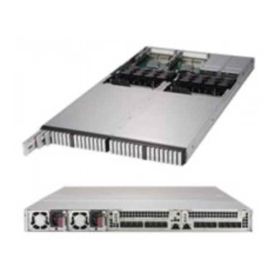
SuperStorage SSG-136R-NR32JBF User's Manual Front Features The 136TS-R1K04JP-R2 is a 1U chassis. See the illustration below for the features included on the front of the chassis. Figure 1-2. Chassis Front View Front Chassis Features Item Feature Description Control Panel Front control panel with LEDs and buttons (see preceding page) -
Page 11: Rear Features
Chapter 1: Introduction Rear Features The illustration below shows the features included on the rear of the chassis. Figure 1-3. Chassis Rear View Rear Chassis Features Item Feature Description 1000W power supply module with LED. Two modules for power Power Supply redundancy. -
Page 12: Ruler Ssd Features
SuperStorage SSG-136R-NR32JBF User's Manual Ruler SSD Features The system contains 32 NVMe Ruler SSDs (RSSDs). The rulers extend from the front of the chassis for access and replacement of drives. Refer to Chapter 3 for instructions on extending the rulers to access the drives. -
Page 13: Controller Board Layout
Chapter 1: Introduction 1.5 Controller Board Layout Below is a layout of the BPN-NVME3-136PL-J. See the following table for jumper descriptions. JPB1 Figure 1-5. Controller Board Layout Quick Reference Table Jumper Description Default Setting JPB1 BMC Enable Pins 1-2 (Enabled) Chassis Intrusion Open Note: The BMC must always be enabled. -
Page 14: Ports
SuperStorage SSG-136R-NR32JBF User's Manual 1.6 Ports Figure 1-6. Rear I/O Panel Rear I/O Ports Item Description IPMI LAN Port 1 IPMI LAN Port 2 PCI-E x16 External Port (Gen 3) UID Button IPMI LAN Ports Two 1Gb IPMI LAN ports (LAN1/2) are located on the I/O back panel. If both ports are plugged in, LAN1 is the active port and LAN2 is redundant. -
Page 15: Chapter 2 System Installation
Chapter 2: System Installation Chapter 2 System Installation 2.1 Overview This chapter provides advice and instructions for mounting your system in a server rack. If your system is not already fully integrated with drives, fans etc., refer to Chapter 3 for details on installing those specific components. -
Page 16: System Precautions
SuperStorage SSG-136R-NR32JBF User's Manual • In single rack installations, stabilizers should be attached to the rack. In multiple rack in- stallations, the racks should be coupled together. • Always verify that the rack is stable before extending a server or other component from the rack. -
Page 17: Circuit Overloading
Chapter 2: System Installation Circuit Overloading Consideration should be given to the connection of the equipment to the power supply circuitry and the effect that any possible overloading of circuits might have on overcurrent protection and power supply wiring. Appropriate consideration of equipment nameplate ratings should be used when addressing this concern. -
Page 18: Installing The System Into A Rack
SuperStorage SSG-136R-NR32JBF User's Manual 2.3 Installing the System into a Rack This section provides information on installing the 136TS-R1K04JP-R2 chassis into a rack unit with the rails provided. Due to the variety of rack units on the market, the assembly procedure might differ slightly. -
Page 19: Releasing The Inner Rails
Chapter 2: System Installation Releasing the Inner Rails Releasing the Inner Rails from the Outer Rails 1. Pull the inner rail out of the outer rail until it is fully extended as illustrated below. 2. Press the locking tab down to release the inner rail. 3. -
Page 20: Installing The Inner Rails On The Chassis
SuperStorage SSG-136R-NR32JBF User's Manual Installing the Inner Rails on the Chassis Installing the Inner Rails 1. Place the inner rail firmly against the side of the chassis, aligning the hooks on the side of the chassis with the holes in the inner rail. -
Page 21: Installing The Outer Rails On The Rack
Chapter 2: System Installation Installing the Outer Rails on the Rack Installing the Outer Rails 1. If your rack has round mounting holes, adjust the fittings on the outer rails. Press the latch at the end of the rail to change from square fittings to round fittings. Figure 2-4. - Page 22 SuperStorage SSG-136R-NR32JBF User's Manual 2. Push the middle rail back into the outer rail. An audible click indicates that the rail is fully inserted. Figure 2-5. Adjusting the Middle Rail 3. Insert the pegs on the rear of the outer rail into the rear rack holes. An audible click indicates that the rail is locked into place.
-
Page 23: Installing The Chassis Onto The Rack
Chapter 2: System Installation Installing the Chassis onto the Rack Installing the Chassis onto the Rack 1. Fully extend the middle rails as illustrated in Figure 2-7. 2. Align the inner rails of the chassis with the middle rails on the rack. 3. -
Page 24: Powering On The System
SuperStorage SSG-136R-NR32JBF User's Manual 2.4 Powering On the System Any time you power on the SSG-136R-NR32JBF system, first perform the following precautions: 1. Verify that all hosts that will use the SSG-136R-NR32JBF are powered off. 2. Connect PCI-E cabling from the hosts to the SSG-136R-NR32JBF. -
Page 25: Chapter 3 Maintenance And Component Installation
SuperStorage SSG-136R-NR32JBF User's Manual Chapter 3 Maintenance and Component Installation This chapter provides instructions on installing and replacing main system components. To prevent compatibility issues, only use components that match the specifications and part numbers given. Installation or replacement of most components require that power first be removed from the system. - Page 26 Chapter 3: Maintenance and Component Installation Side Screws Figure 3-1. Removing the Chassis Cover...
-
Page 27: Chassis Components
SuperStorage SSG-136R-NR32JBF User's Manual 3.3 Chassis Components Ruler Drives Your system likely came with drives installed. The SSG-136R-NR32JBF supports 32 hot- swappable RSSDs (Ruler SSDs). Drives are installed and removed by extending a ruler from the chassis. Note that NVMe RSSDs must be prepared prior to removal from the system, as detailed below. - Page 28 Chapter 3: Maintenance and Component Installation 2. Next, find the PCI information of the target SSD. The example below is for /dev/nvme17n1 # ls -l /sys/block/nvme17n1 lrwxrwxrwx 1 root root 0 Jul 16 14:02 /sys/block/nvme17n1 -> ../devices/pci0000:2d/0000:2d:00.0/0000:2e:00.0/0000: 2f:04.0/0000:30:00.0/0000:31:01.0/0000:44:00.0/0000:45:01.0/0000:47:00.0/nvme/nvme17/ nvme17n1 /dev/nvme17n1 Bus:Device.Function More information of /dev/nvme17n1 could be probed for cross-reference if needed # udevadm info -n /dev/nvme17n1 -a …...
- Page 29 SuperStorage SSG-136R-NR32JBF User's Manual Figure 3-2. JBOF Pooled NVMe Storage View As shown in Figure 3-2, the target SSD is in slot 17, with the SSD Vendor/Model/Serial matching what we probed. Besides slot labeling on the drive tray, the slot position can also be located using the Locate function on the BMC GUI (as shown above).
-
Page 30: Windows Environment
Chapter 3: Maintenance and Component Installation 5. The final step is to hot insert a replacement SSD. The replacement SSD can simply be hot inserted. After the OS discovers the newly inserted SSD, it’s ready for configuration and access. Windows Environment Examples listed here were done under Windows Server 2016. - Page 31 SuperStorage SSG-136R-NR32JBF User's Manual All the installed Intel SSD information can also be retrieved with the Intel SSD data center tool. #isdct show –intelssd … - Intel SSD DC P4500 Series PHLF720400A54P0IGN - Serial number Bootloader : 0133 DevicePath : \\\\.\\PHYSICALDRIVE25 ...
- Page 32 Chapter 3: Maintenance and Component Installation With the Locate function as shown above, the slot position of the target SSD can be located. When located, the slot LED will blink red or the RSSD LED will blink blue. 2. Next, prepare the target NVMe SSD for hot removal. From Start (Right Click)\Control Panel\Hardware\Devices and Printers, all NVMe SSDs will be listed: Figure 3-5.
- Page 33 SuperStorage SSG-136R-NR32JBF User's Manual 3. Before removing or ejecting any SSD, confirm its location information by right clicking its icon and opening the Hardware tab from the Properties selection: Figure 3-6. Hardware Tab If all the NVMe SSDs installed are from a single JBOF and the host detected all 32 NVMe...
- Page 34 Chapter 3: Maintenance and Component Installation Please wait for the target SSD to be fully removed from host, confirmed by: • Its icon removed from the Devices panel of Devices and Printers • Its disk number and information removed from Disk management •...
- Page 35 SuperStorage SSG-136R-NR32JBF User's Manual Under the Details tab, select Physical Device Object Name from the Property pull-down menu: Figure 3-8. Finding the Physical Device Object Name (Method 1)
- Page 36 Chapter 3: Maintenance and Component Installation • The physical device object name of a disk may also be obtained Devices and Printer Management. Open the Property window of a SSD by right clicking its icon and select the Properties windows as shown below: Figure 3-9.
- Page 37 SuperStorage SSG-136R-NR32JBF User's Manual Extending a Ruler 1. Press the button at the top of the ruler to pop out the handle. 2. Grasp the handle and latches and use them to extend the ruler out of the chassis. Button...
-
Page 38: System Cooling
Chapter 3: Maintenance and Component Installation System Cooling Eight 4-cm hot-swap fans provide the cooling for the system. It is very important that the chassis top cover is properly installed and forms a seal in order for the cooling air to circulate properly through the chassis and cool the components. -
Page 39: Power Supply
If either of the two power supply modules fail, the other will take the full load and allow the system to continue operation without interruption. The Power Fail LED illuminates until the failed module has been replaced. Replacements can be ordered directly from Supermicro (see contact information in the Preface). The power supply modules have a hot-swap capability, so you can replace the failed module without powering down the system. -
Page 40: Pci-E Cables
PCI-E x8 cables, and eight servers with single PCI-E x8 cables. AOC-SLG3-4X4P AOC-SLG3-4X4P Server with two or more Host Interface Cards External PCI-E Cables Figure 3-13. Single Server with Multiple Interface Cards (Dual PCI-E x8 Cables) * The AOC-SLG3-4X4P User's Guide is available on the Supermicro website. - Page 41 SuperStorage SSG-136R-NR32JBF User's Manual AOC-SLG3-4X4P Server #1 with Host Interface Card External PCI-E Cables Server #3 Server #4 Server #2 with Host Interface Card AOC-SLG3-4X4P Figure 3-14. Four Servers (Dual PCI-E x8 Cables)
- Page 42 Chapter 3: Maintenance and Component Installation Server #1 Server #2 Server #3 Server #4 AOC-SLG3-4X4P AOC-SLG3-4X4P AOC-SLG3-4X4P AOC-SLG3-4X4P External PCI-E Cables AOC-SLG3-4X4P AOC-SLG3-4X4P AOC-SLG3-4X4P AOC-SLG3-4X4P Server #5 Server #6 Server #7 Server #8 Figure 3-15. Eight Servers (Single PCI-E x8 Cables)
-
Page 43: Pci-E Expansion Cards
SuperStorage SSG-136R-NR32JBF User's Manual PCI-E Expansion Cards The SSG-136R-NR32JBF can accommodate up to two full-height PCI-E expansion cards in the rear slots. These are only used for NVMeoF configurations, 6-host configurations, and 12-host configurations. Installing an Add-on Card Begin by removing power from the system as described in Section 3.1 and removing the cover as described in Section 3.2. -
Page 44: Appendix A Standardized Warning Statements For Ac Systems
Supermicro's Technical Support department for assistance. Only certified technicians should attempt to install or configure components. Read this appendix in its entirety before installing or configuring components in the Supermicro chassis. These warnings may also be found on our website at http://www.supermicro.com/about/... - Page 45 Appendix A: Standardized Warning Statements Warnung WICHTIGE SICHERHEITSHINWEISE Dieses Warnsymbol bedeutet Gefahr. Sie befinden sich in einer Situation, die zu Verletzungen führen kann. Machen Sie sich vor der Arbeit mit Geräten mit den Gefahren elektrischer Schaltungen und den üblichen Verfahren zur Vorbeugung vor Unfällen vertraut. Suchen Sie mit der am Ende jeder Warnung angegebenen Anweisungsnummer nach der jeweiligen Übersetzung in den übersetzten Sicherheitshinweisen, die zusammen mit diesem Gerät ausgeliefert wurden.
- Page 46 SuperStorage SSG-136R-NR32JBF User's Manual . ٌ ا ك ً ف حالة و ٌ يك أى تتسبب ف اصابة جسذ ة ٌ هذا الزهز ع ٌ خطز !تحذ ز قبل أى تعول عىل أي هعذات،يك عىل علن بالوخاطز ال ا ٌجوة عي الذوائز...
- Page 47 Appendix A: Standardized Warning Statements Warnung Vor dem Anschließen des Systems an die Stromquelle die Installationsanweisungen lesen. ¡Advertencia! Lea las instrucciones de instalación antes de conectar el sistema a la red de alimentación. Attention Avant de brancher le système sur la source d'alimentation, consulter les directives d'installation. .יש...
- Page 48 SuperStorage SSG-136R-NR32JBF User's Manual Warnung Dieses Produkt ist darauf angewiesen, dass im Gebäude ein Kurzschluss- bzw. Überstromschutz installiert ist. Stellen Sie sicher, dass der Nennwert der Schutzvorrichtung nicht mehr als: 250 V, 20 A beträgt. ¡Advertencia! Este equipo utiliza el sistema de protección contra cortocircuitos (o sobrecorrientes) del edificio.
- Page 49 Appendix A: Standardized Warning Statements Power Disconnection Warning Warning! The system must be disconnected from all sources of power and the power cord removed from the power supply module(s) before accessing the chassis interior to install or remove system components. 電源切断の警告...
- Page 50 SuperStorage SSG-136R-NR32JBF User's Manual يجب فصم اننظاو من جميع مصادر انطاقت وإ ز انت سهك انكهرباء من وحدة امداد انطاقت قبم انىصىل إىن امنناطق انداخهيت نههيكم نتثبيج أو إ ز انت مكىناث الجهاز 경고! 시스템에 부품들을 장착하거나 제거하기 위해서는 섀시 내부에 접근하기 전에 반드시 전원...
- Page 51 Appendix A: Standardized Warning Statements Attention Il est vivement recommandé de confier l'installation, le remplacement et la maintenance de ces équipements à des personnels qualifiés et expérimentés. !אזהרה .צוות מוסמך בלבד רשאי להתקין, להחליף את הציוד או לתת שירות עבור הציוד واملدربيه...
- Page 52 SuperStorage SSG-136R-NR32JBF User's Manual Warnung Diese Einheit ist zur Installation in Bereichen mit beschränktem Zutritt vorgesehen. Der Zutritt zu derartigen Bereichen ist nur mit einem Spezialwerkzeug, Schloss und Schlüssel oder einer sonstigen Sicherheitsvorkehrung möglich. ¡Advertencia! Esta unidad ha sido diseñada para instalación en áreas de acceso restringido. Sólo puede obtenerse acceso a una de estas áreas mediante la utilización de una herramienta especial,...
- Page 53 Appendix A: Standardized Warning Statements Battery Handling Warning! There is the danger of explosion if the battery is replaced incorrectly. Replace the battery only with the same or equivalent type recommended by the manufacturer. Dispose of used batteries according to the manufacturer's instructions 電池の取り扱い...
- Page 54 SuperStorage SSG-136R-NR32JBF User's Manual هناك خطر من انفجار يف حالة اسحبذال البطارية بطريقة غري صحيحة فعليل اسحبذال البطارية فقط بنفس النىع أو ما يعادلها مام أوصث به الرشمة املصنعة جخلص من البطاريات املسحعملة وفقا لحعليامت الرشمة الصانعة 경고! 배터리가 올바르게 교체되지 않으면 폭발의 위험이 있습니다. 기존 배터리와 동일하거나 제...
- Page 55 Appendix A: Standardized Warning Statements ¡Advertencia! Puede que esta unidad tenga más de una conexión para fuentes de alimentación. Para cortar por completo el suministro de energía, deben desconectarse todas las conexiones. Attention Cette unité peut avoir plus d'une connexion d'alimentation. Pour supprimer toute tension et tout courant électrique de l'unité, toutes les connexions d'alimentation doivent être débranchées.
- Page 56 SuperStorage SSG-136R-NR32JBF User's Manual Backplane Voltage Warning! Hazardous voltage or energy is present on the backplane when the system is operating. Use caution when servicing. バックプレーンの電圧 システムの稼働中は危険な電圧または電力が、 バックプレーン上にかかっています。 修理する際には注意く ださい。 警告 当系统正在进行时,背板上有很危险的电压或能量,进行维修时务必小心。 警告 當系統正在進行時,背板上有危險的電壓或能量,進行維修時務必小心。 Warnung Wenn das System in Betrieb ist, treten auf der Rückwandplatine gefährliche Spannungen oder Energien auf.
- Page 57 Appendix A: Standardized Warning Statements هناك خطز مه التيار الكهزبايئ أوالطاقة املىجىدة عىل اللىحة عندما يكىن النظام يعمل كه حذ ر ا عند خدمة هذا الجهاس 경고! 시스템이 동작 중일 때 후면판 (Backplane)에는 위험한 전압이나 에너지가 발생 합니다. 서비스 작업 시 주의하십시오. Waarschuwing Een gevaarlijke spanning of energie is aanwezig op de backplane wanneer het systeem in gebruik is.
- Page 58 SuperStorage SSG-136R-NR32JBF User's Manual תיאום חוקי החשמל הארצי !אזהרה .התקנת הציוד חייבת להיות תואמת לחוקי החשמל המקומיים והארציים تركيب املعدات الكهربائية يجب أن ميتثل للقىاويه املحلية والىطىية املتعلقة بالكهرباء 경고! 현 지역 및 국가의 전기 규정에 따라 장비를 설치해야 합니다.
- Page 59 Appendix A: Standardized Warning Statements Attention La mise au rebut ou le recyclage de ce produit sont généralement soumis à des lois et/ou directives de respect de l'environnement. Renseignez-vous auprès de l'organisme compétent. סילוק המוצר !אזהרה .סילוק סופי של מוצר זה חייב להיות בהתאם להנחיות וחוקי המדינה التخلص...
- Page 60 SuperStorage SSG-136R-NR32JBF User's Manual Warnung Gefährlich Bewegende Teile. Von den bewegenden Lüfterblätter fern halten. Die Lüfter drehen sich u. U. noch, wenn die Lüfterbaugruppe aus dem Chassis genommen wird. Halten Sie Finger, Schraubendreher und andere Gegenstände von den Öffnungen des Lüftergehäuses entfernt.
- Page 61 Verbindungskabeln, Stromkabeln und/oder Adapater, die Ihre örtlichen Sicherheitsstandards einhalten. Der Gebrauch von anderen Kabeln und Adapter können Fehlfunktionen oder Feuer verursachen. Die Richtlinien untersagen das Nutzen von UL oder CAS zertifizierten Kabeln (mit UL/CSA gekennzeichnet), an Geräten oder Produkten die nicht mit Supermicro gekennzeichnet sind.
- Page 62 حجم املوصل والقابس السليم. استخدام أي كابالت ومحوالت أخرى قد يتسبب يف عطل أو حريق. يحظر قانون السالمة لألجهزة الكهربائية واملعدات استخدام الكابالت املعتمدة من قبلUL أوCSA ( والتي تحمل عالمةUL/CSA) مع أي معدات أخرى غري املنتجات املعنية واملحددة من قبلSupermicro.
- Page 63 사항을 준수하여 제공되거나 지정된 연결 혹은 구매 케이블, 전원 케이블 및 AC 어댑터를 사용하십시오. 다른 케이블이나 어댑터를 사용하면 오작동이나 화재가 발생할 수 있습니다. 전기 용품 안전법은 UL 또는 CSA 인증 케이블 (코드에 UL / CSA가 표시된 케이블)을 Supermicro 가 지정한 제품 이외의 전기 장치에 사용하는 것을 금지합니다. Stroomkabel en AC-Adapter...
-
Page 64: Appendix B System Specifications
SuperStorage SSG-136R-NR32JBF User's Manual Appendix B System Specifications Drive Bays 32 NVMe Ruler SSDs PCI Expansion Slots Two PCI Express 3.0 x16 Slots Four External PCI Express 3.0 x16 Ports Controller Board BPN-NVME3-136PL-J Chassis 136TS-R1K04JP-R2; 1U Rackmount, (WxHxD) 17.26 x 1.71 x 31.95 in. (438.4 x 43.6 x 811.7 mm) -
Page 65: Appendix C Drive Assignment
Appendix C: Drive Assignment Appendix C Drive Assignment C.1 Overview After installing the SSG-136R-NR32JBF system, you must assign drives to hosts. This appendix provides information about drive mappings and procedures for reassigning drives to different hosts. Refer to the Web GUI or command line interface sections in this appendix for your preferred procedure. - Page 66 SuperStorage SSG-136R-NR32JBF User's Manual C.2 Drive Slots Endpoint Mapping Each physical drive is assigned an "endpoint" number that is different from the physical slot number. The following tables provide an overview of endpoint mapping for drive slots in a four-host and eight-host configuration.
- Page 67 Appendix C: Drive Assignment C.3 Assigning a Drive from the GUI Drive assignment from the Web GUI requires a computer with access to the network that contains the SSG-136R-NR32JBF system. Optimize drive performance by assigning the drives used by each host across the PCI-E switches (RSSD trays) and across the bays within each tray (see figure on page 10).
- Page 68 SuperStorage SSG-136R-NR32JBF User's Manual 6. Perform step 5 for all drives you want to assign/reassign. 7. When finished, click Apply to apply all changes. 8. To revert, click Cancel. Note: A device needs to be On for Pooled NVMe Storage to display any information.
- Page 69 Appendix C: Drive Assignment In the following example of a 4-host configuration, endpoint 19 (drive 22) represents the only drive assigned to Zone 1: "@odata.context": "/redfish/v1/$metadata#Zone.Zone", "@odata.id": "/redfish/v1/Fabrics/1/Zones/1", "@odata.type": "#Zone.Zone", "Description": "PCIe Zone 1", "Id": "1", "Links": { "Endpoints": [ "@odata.id": "/redfish/v1/Fabrics/1/Endpoints/1"...
- Page 70 SuperStorage SSG-136R-NR32JBF User's Manual Reassigning a Drive 1. To change drive assignment, you must first create a .txt file that includes your changes in JSON format. For example: "Endpoints": [ "@odata.id": "/redfish/v1/Fabrics/1/Endpoints/1" "@odata.id": "/redfish/v1/Fabrics/1/Endpoints/7" "@odata.id": "/redfish/v1/Fabrics/1/Endpoints/5" In the above example of a 4-host configuration, endpoint 19 (drive 22) was removed from Zone 1, and endpoints 7 and 5 (drives 26 and 24) were added to Zone 1.
- Page 71 Appendix C: Drive Assignment C.5 Obtaining the System IP Address Drive reassignment requires the IP address of the SSG-136R-NR32JBF system. Perform the following procedure to obtain the system IP address. If DHCP is detected, a dynamic IP address is assigned to the system. If DHCP is not detected, the default IP address is 192.168.1.99.
-
Page 72: Appendix D Firmware Updates
SuperStorage SSG-136R-NR32JBF User's Manual Appendix D Firmware Updates D.1 Updating Switch Configuration Use IPMI to update the configuration of the JBOF switches. 1. Log into the IPMI. The default Username and Password are ADMIN / ADMIN. 2. Under the Maintenance tab, select JBOF FW Update. - Page 73 Appendix D: Firmware Updates 4. Click Choose File to select configuration file, and click the Update button. 5. Click OK to confirm. 6. Click OK to finish. 7. After all intended switches are configured, please reset the system to complete the update.
- Page 74 SuperStorage SSG-136R-NR32JBF User's Manual D.2 Updating the BMC Firmware Use IPMI to update the BMC firmware. 1. Log into the IPMI. By default, both Username and Password are ADMIN 2. Under the Maintenance tab, select Firmware Update. 3. Click the Enter Update Mode button.
- Page 75 Appendix D: Firmware Updates 5. Clear all check box options and click the Start Upgrade button. 6. Click OK to confirm and wait. The JBOF system reboots to complete the update.
Need help?
Do you have a question about the SuperStorage SSG-136R-NR32JBF and is the answer not in the manual?
Questions and answers