
Related Manuals for LevelOne FGL-2870


Summary of Contents for LevelOne FGL-2870
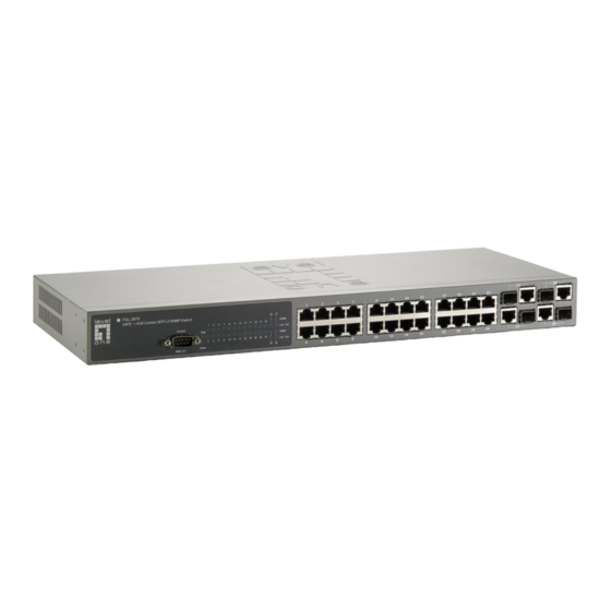
- Page 1 LevelOne FGL-2870 24 FE + 4 GE Combo SFP L2 SNMP Switch Installation Guide Version 1.0...
- Page 3 Installation Guide Fast Ethernet Switch Combo Layer 2 SNMP Switch with 24 10/100BASE-T (RJ-45) Ports, and 4 Combination Gigabit (RJ-45/SFP) Ports...
- Page 4 FGL-2870 E122009-WM-R01 149100000059A...
- Page 5 Compliances and Safety Warnings FCC - Class A This equipment has been tested and found to comply with the limits for a Class A digital device, pursuant to part 15 of the FCC Rules. These limits are designed to provide reasonable protection against harmful interference when the equipment is operated in a commercial environment.
- Page 6 CE Mark Declaration of Conformance for EMI and Safety (EEC) This information technology equipment complies with the requirements of the Council Directive 89/336/EEC on the Approximation of the laws of the Member States relating to Electromagnetic Compatibility and 73/23/EEC for electrical equipment used within certain voltage limits and the Amendment Directive 93/68/EEC.
- Page 7 Safety Compliance Warning: Fiber Optic Port Safety When using a fiber optic port, never look at the transmit laser while it is powered on. Also, never look directly at the fiber TX port and fiber cable CLASS I LASER DEVICE ends when they are powered on.
- Page 8 Power Cord Set U.S.A. and Canada The cord set must be UL-approved and CSA certified. The minimum specifications for the flexible cord are: - No. 18 AWG - not longer than 2 meters, or 16 AWG. - Type SV or SJ - 3-conductor The cord set must have a rated current capacity of at least 10 A The attachment plug must be an earth-grounding type with NEMA...
- Page 9 France et Pérou uniquement: Ce groupe ne peut pas être alimenté par un dispositif à impédance à la terre. Si vos alimentations sont du type impédance à la terre, ce groupe doit être alimenté par une tension de 230 V (2 P+T) par le biais d’un transformateur d’isolement à rapport 1:1, avec un point secondaire de connexion portant l’appellation Neutre et avec raccordement direct à...
- Page 10 Stromkabel . Dies muss von dem Land, in dem es benutzt wird geprüft werden: Schweiz Dieser Stromstecker muß die SEV/ASE 1011Bestimmungen ein- halten. Europe Das Netzkabel muß vom Typ HO3VVF3GO.75 (Mindestanforderung) sein und die Aufschrift <HAR> oder <BASEC> tragen. Der Netzstecker muß die Norm CEE 7/7 erfüllen (”SCHUKO”). Warnings and Cautionary Messages Warning: This product does not contain any serviceable user parts.
- Page 11 Environmental Statement The manufacturer of this product endeavours to sustain an environmentally-friendly policy throughout the entire production process. This is achieved though the following means: • Adherence to national legislation and regulations on environmental production standards. • Conservation of operational resources. •...
- Page 12 viii...
-
Page 13: Table Of Contents
Contents Chapter 1: Introduction Overview Switch Architecture Network Management Options Description of Hardware 10/100BASE-T Ports SFP Slots Port and System Status LEDs Power Supply Sockets Features and Benefits Connectivity Expandability Performance Management Chapter 2: Network Planning Introduction to Switching Application Examples Collapsed Backbone Network Aggregation Plan Remote Connection with Fiber Cable... - Page 14 Contents Chapter 4: Making Network Connections Connecting Network Devices Twisted-Pair Devices Cabling Guidelines Connecting to PCs, Servers, Hubs and Switches Network Wiring Connections Fiber Optic SFP Devices Connectivity Rules 1000BASE-T Cable Requirements 1000 Mbps Gigabit Ethernet Collision Domain 100 Mbps Fast Ethernet Collision Domain 10 Mbps Ethernet Collision Domain Cable Labeling and Connection Records Appendix A: Troubleshooting...
- Page 15 Tables Table 1-1 FGL-2870 Port Status LEDs Table 1-2 System Status LEDs Table 3-1. Serial Cable Wiring Table 4-1. Maximum 1000BASE-T Gigabit Ethernet Cable Length Table 4-2. Maximum 1000BASE-SX Gigabit Ethernet Cable Length Table 4-3. Maximum 1000BASE-LX Gigabit Ethernet Cable Length Table 4-4.
- Page 16 Figures Figure 1-1. FGL-2870 Front and Rear Panels Figure 1-2. FGL-2870 Port Status LEDs Figure 1-3. FGL-2870 System Status LED Figure 1-4. FGL-2870 Power Supply Sockets Figure 2-1. Collapsed Backbone Figure 2-2. Network Aggregation Plan Figure 2-3. Remote Connection with Fiber Cable Figure 2-4.
-
Page 17: Chapter 1: Introduction
Chapter 1: Introduction Overview The FGL-2870 switch is a intelligent switch with 24 10/100BASE-T ports, and four Gigabit combination ports that are comprised of a RJ-45 port and an SFP transceiver slot. There is also an SNMP-based management agent embedded on the main board. -
Page 18: Switch Architecture
Introduction Switch Architecture This switch employs a wire-speed, non-blocking switching fabric. This permits simultaneous wire-speed transport of multiple packets at low latency on all ports. These switches also features full-duplex capability on all ports, which effectively doubles the bandwidth of each connection. his switch uses store-and-forward switching to ensure maximum data integrity. -
Page 19: Port And System Status Leds
The LEDs, which are located on the front panel for easy viewing, are shown below and described in the following table. Combination Gigabit Port Status LEDs Port Status LEDs Figure 1-2. FGL-2870 Port Status LEDs Table 1-1 FGL-2870 Port Status LEDs Condition Status... -
Page 20: Power Supply Sockets
Introduction System Status LEDs Figure 1-3. FGL-2870 System Status LED Table 1-2 System Status LEDs Condition Status On Green Internal power is operating normally. (Power) On Amber Internal power supply has failed. Power off or failure. DIAG On Green System self-diagnostic test successfully completed. -
Page 21: Features And Benefits
Features and Benefits Features and Benefits Connectivity • 24 10/100BASE-T ports plus 4 Gigabit combination ports (RJ-45/SFP). • Auto-negotiation enables each RJ-45 port to automatically select the optimum speed (10 or 100 Mbps), and the communication mode (half or full duplex) if this feature is supported by the attached device;... - Page 22 Introduction...
-
Page 23: Chapter 2: Network Planning
Chapter 2: Network Planning Introduction to Switching A network switch allows simultaneous transmission of multiple packets via non-crossbar switching. This means that it can partition a network more efficiently than bridges or routers. The switch has, therefore, been recognized as one of the most important building blocks for today’s networking technology. -
Page 24: Application Examples
Network Planning Application Examples This switch isnot only designed to segment your network, but also to provide a wide range of options in setting up network connections. Some typical applications are described in the following pages. Collapsed Backbone This switch isan excellent choice for mixed Ethernet, Fast Ethernet, and Gigabit Ethernet installations where significant growth is expected in the near future. -
Page 25: Network Aggregation Plan
Application Examples Network Aggregation Plan With 24 parallel bridging ports (i.e., 24 distinct collision domains), the switch can collapse a complex network down into a single efficient bridged node, increasing overall bandwidth and throughput. In the figure below, the 10/100BASE-TX ports on the switch are providing 100 Mbps connectivity through layer 2 switches. -
Page 26: Remote Connection With Fiber Cable
Network Planning Remote Connection with Fiber Cable Fiber optic technology allows for longer cabling than any other media type. A 1000BASE-SX (MMF) link can connect to a site up to 550 meters away, a 1000BASE-LX (SMF) link up to 5 km, and a 1000BASE-LH link up to 70 km. This allows the switch to serve as a collapsed backbone, providing direct connectivity for a widespread LAN. -
Page 27: Making Vlan Connections
Application Examples Making VLAN Connections This switch supports VLANs which can be used to organize any group of network nodes into separate broadcast domains. VLANs confine broadcast traffic to the originating group, and can eliminate broadcast storms in large networks. This provides a more secure and cleaner network environment. -
Page 28: Application Notes
Network Planning Application Notes Full-duplex operation only applies to point-to-point access (such as when a switch is attached to a workstation, server or another switch). When the switch is connected to a hub, both devices must operate in half-duplex mode. Avoid using flow control on a port connected to a hub unless it is actually required to solve a problem. -
Page 29: Chapter 3: Installing The Switch
Chapter 3: Installing the Switch Selecting a Site Switch units can be mounted in a standard 19-inch equipment rack or on a flat surface. Be sure to follow the guidelines below when choosing a location. • The site should: • be at the center of all the devices you want to link and near a power outlet. •... -
Page 30: Equipment Checklist
Then, before beginning the installation, be sure you have all other necessary installation equipment. Package Contents • FGL-2870 Fast Ethernet Switch • Four adhesive foot pads • Bracket Mounting Kit containing two brackets and eight screws for attaching the brackets to the switch •... -
Page 31: Mounting
Mounting Mounting The switch units can be mounted in a standard 19-inch equipment rack or on a desktop or shelf. Mounting instructions for each type of site follow. Rack Mounting Before rack mounting the switch, pay particular attention to the following factors: •... -
Page 32: Desktop Or Shelf Mounting
Installing the Switch Mount the device in the rack, using four rack-mounting screws (not provided). Figure 3-3. Installing the Switch in a Rack If installing a single switch only, turn to "Connecting to a Power Source" at the end of this chapter. If installing multiple switches, mount them in the rack, one below the other, in any order. -
Page 33: Installing An Optional Sfp Transceiver
Installing an Optional SFP Transceiver Installing an Optional SFP Transceiver Figure 3-5. Inserting an SFP Transceiver into a Slot The switch supports 1000BASE-SX and 1000BASE-LX, 1000BASE-LH and other SFP-compatible transceivers. To install an SFP transceiver, do the following: Consider network and cabling requirements to select an appropriate SFP transceiver type. -
Page 34: Connecting To A Power Source
Installing the Switch Connecting to a Power Source To connect a device to a power source: Insert the power cable plug directly into the socket located at the back of the device. Figure 3-6. Power Sockets Plug the other end of the cable into a grounded, 3-pin socket. Note: For International use, you may need to change the AC line cord. -
Page 35: Connecting To The Console Port
Connecting to the Console Port Connecting to the Console Port The DB-9 serial port on the switch’s front panel is used to connect to the switch for out-of-band console configuration. The on-board configuration program can be accessed from a terminal or a PC running a terminal emulation program. The pin assignments used to connect to the serial port are described in the following figure and table. - Page 36 Installing the Switch...
-
Page 37: Chapter 4: Making Network Connections
Chapter 4: Making Network Connections Connecting Network Devices These switches are designed to interconnect multiple segments (or collision domains). It can be connected to network cards in PCs and servers, as well as to hubs, switches or routers. It may also be connected to devices using optional SFP tranceivers. -
Page 38: Network Wiring Connections
Making Network Connections If the device is a PC card and the switch is in the wiring closet, attach the other end of the cable segment to a modular wall outlet that is connected to the wiring closet. (See "Network Wiring Connections" on page 4-2.) Otherwise, attach the other end to an available port on the switch. -
Page 39: Fiber Optic Sfp Devices
Fiber Optic SFP Devices Fiber Optic SFP Devices An optional Gigabit SFP transceiver (1000BASE-SX, 1000BASE-LX, or 1000BASE-LH) can be used for a backbone connection between switches, or for connecting to a high-speed server. Each multimode fiber optic port requires 50/125 or 62.5/125 micron multimode fiber optic cabling with an LC connector at both ends. -
Page 40: Connectivity Rules
Making Network Connections Figure 4-3. Making Fiber Port Connections As a connection is made, check the Link LED on the switch corresponding to the port to be sure that the connection is valid. The 1000BASE-SX, 1000BASE-LX and 1000BASE-LH fiber optic ports operate at 1 Gbps full duplex, with auto-negotiation of flow control. -
Page 41: 1000 Mbps Gigabit Ethernet Collision Domain
Connectivity Rules 1000 Mbps Gigabit Ethernet Collision Domain Table 4-1. Maximum 1000BASE-T Gigabit Ethernet Cable Length Cable Type Maximum Cable Length Connector Category 5, 5e, 6 100-ohm UTP or STP 100 m (328 ft) RJ-45 Table 4-2. Maximum 1000BASE-SX Gigabit Ethernet Cable Length Fiber Size Fiber Bandwidth Maximum Cable Length... -
Page 42: Cable Labeling And Connection Records
Making Network Connections Cable Labeling and Connection Records When planning a network installation, it is essential to label the opposing ends of cables and to record where each cable is connected. Doing so will enable you to easily locate inter-connected devices, isolate faults and change your topology without need for unnecessary time consumption. -
Page 43: Appendix A: Troubleshooting
Appendix A: Troubleshooting Diagnosing Switch Indicators Table A-1. Troubleshooting Chart Symptom Action Power LED is Off • Power supply is disconnected. • Check connections between the switch, the power cord, and the wall outlet. • Contact your dealer for assistance. Power LED is Amber •... -
Page 44: In-Band Access
Troubleshooting In-Band Access You can access the management agent in the switch from anywhere within the attached network using Telnet, a Web browser, or other network management software tools. However, you must first configure the switch with a valid IP address, subnet mask, and default gateway. -
Page 45: Appendix B: Cables
Appendix B: Cables Twisted-Pair Cable and Pin Assignments For 10/100BASE-TX connections, a twisted-pair cable must have two pairs of wires. For 1000BASE-T connections the twisted-pair cable must have four pairs of wires. Each wire pair is identified by two different colors. For example, one wire might be green and the other, green with white stripes. -
Page 46: Straight-Through Wiring
Cables Table B-1. 10/100BASE-TX MDI and MDI-X Port Pinouts MDI Signal Name MDI-X Signal Name Transmit Data plus (TD+) Receive Data plus (RD+) Transmit Data minus (TD-) Receive Data minus (RD-) Receive Data plus (RD+) Transmit Data plus (TD+) Receive Data minus (RD-) Transmit Data minus (TD-) Not used Not used... -
Page 47: 1000Base-T Pin Assignments
Twisted-Pair Cable and Pin Assignments 10/100BASE-TX Crossover Cable White/Orange Stripe Orange White/Green Stripe End A End B Blue White/Blue Stripe Green White/Brown Stripe Brown Figure B-3. Crossover Wiring 1000BASE-T Pin Assignments All 1000BASE-T ports support automatic MDI/MDI-X operation, so you can use straight-through cables for all network connections to PCs or servers, or to other switches or hubs. - Page 48 Cables Cable Testing for Existing Category 5 Cable Installed Category 5 cabling must pass tests for Attenuation, Near-End Crosstalk (NEXT), and Far-End Crosstalk (FEXT). This cable testing information is specified in the ANSI/TIA/EIA-TSB-67 standard. Additionally, cables must also pass test parameters for Return Loss and Equal-Level Far-End Crosstalk (ELFEXT).
-
Page 49: Appendix C: Specifications
Appendix C: Specifications Physical Characteristics Ports 24 10/100BASE-TX, with auto-negotiation 4 Combination Gigabit Ports (RJ-45/SFP) Network Interface Ports 1-24: RJ-45 connector, auto MDI/X 10BASE-T: RJ-45 (100-ohm, UTP cable; Category 3 or better) 100BASE-TX: RJ-45 (100-ohm, UTP cable; Category 5 or better) Buffer Architecture 4 Mbits Aggregate Bandwidth... -
Page 50: Switch Features
Specifications Temperature Operating: 0 to 45 °C (32 to 113 °F) Storage: -40 to 70 °C (-40 to 158 °F) Humidity Operating: 10% to 90% (non-condensing) Power Supply Internal, auto-ranging transformer: 100 to 240 V, 50-60 Hz, 0.8 A Power Consumption 30 Watts maximum Maximum Current 0.25 A @ 115 VAC... -
Page 51: Standards
Standards Standards IEEE 802.3 Ethernet IEEE 802.3u Fast Ethernet IEEE 802.3z and 802.3ab Gigabit Ethernet IEEE 802.1D (Bridging) IEEE 802.3x full-duplex flow control IEEE 802.1Q (Virtual LAN) ISO/IEC 8802-3 Compliances CE Mark Emissions FCC Class A Industry Canada Class A EN55022 (CISPR 22) Class A EN 61000-3-2/3 VCCI Class A... - Page 52 Specifications...
-
Page 53: Glossary
Glossary 10BASE-T IEEE 802.3 specification for 10 Mbps Ethernet over two pairs of Category 3, 4, or 5 UTP cable. 100BASE-TX IEEE 802.3u specification for 100 Mbps Ethernet over two pairs of Category 5 UTP cable. 1000BASE-LH Specification for long-haul Gigabit Ethernet over two strands of 9/125 micron core fiber cable. - Page 54 Glossary CSMA/CD CSMA/CD (Carrier Sense Multiple Access/Collision Detect) is the communication method employed by Ethernet, Fast Ethernet, or Gigabit Ethernet. End Station A workstation, server, or other device that does not forward traffic. Ethernet A network communication system developed and standardized by DEC, Intel, and Xerox, using baseband transmission, CSMA/CD access, logical bus topology, and coaxial cable.
- Page 55 Glossary IEEE 802.3x Defines Ethernet frame start/stop requests and timers used for flow control on full-duplex links. IEEE 802.3z Defines CSMA/CD access method and physical layer specifications for 1000BASE Gigabit Ethernet. LAN Segment Separate LAN or collision domain. Light emitting diode used for monitoring a device or network condition. Local Area Network (LAN) A group of interconnected computer and support devices.
- Page 56 Glossary Transmission Control Protocol/Internet Protocol (TCP/IP) Protocol suite that includes TCP as the primary transport protocol, and IP as the network layer protocol. Unshielded twisted-pair cable. Virtual LAN (VLAN) A Virtual LAN is a collection of network nodes that share the same collision domain regardless of their physical location or connection point in the network.
-
Page 57: Index
Index Numerics 10 Mbps connectivity rules 4-5 electrical interference, avoiding 3-1 100 Mbps connectivity rules 4-5 equipment checklist 3-2 1000BASE-T Ethernet connectivity rules 4-5 pin assignments B-3 ports 1-2 100BASE-TX Fast Ethernet connectivity rules 4-5 pin assignments B-1 features C-2 ports 1-2 management 1-5 10BASE-T... - Page 58 Index Web-based 1-2 pinouts B-3 mounting the switch rubber foot pads, attaching 3-4 in a rack 3-3 on a desktop or shelf 3-4 multimode fiber optic cables 4-3 screws for rack mounting 3-2 site selelction 3-1 SNMP agent 1-2 network specifications connections 4-1 compliances C-3...
- Page 60 FGL-2870 E122009-MW-R01 149100000059A...
Need help?
Do you have a question about the FGL-2870 and is the answer not in the manual?
Questions and answers