
Related Manuals for Texas Instruments LM3639A


Summary of Contents for Texas Instruments LM3639A
- Page 1 Using the LM3639A Evaluation Module User's Guide Literature Number: SNVU211 March 2013...
-
Page 2: Input/Output Connector Description
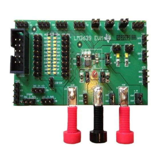
The Texas Instruments LM3639YFQAEVM evaluation module (EVM) helps designers evaluate the operation and performance of the LM3639A Single Chip 40V Backlight + 1.5A Flash LED Driver. The low- voltage, high-current flash LED driver is a synchronous boost which provides the power for a single flash LED at up to 1.5A or dual LEDs at up to 750 mA each. - Page 3 J22 - PWM- This pin provides an external method for adjusting the backlight LED brightness. The PWM pin is connected to ground via a 300 kΩ resistor internal to the LM3639A. To externally drive this pin, either connect a control signal directly to the PWM pin of the connector or place a jumper between connector pins PWM and PWM0.
-
Page 4: Operation
Enable the device and to configure it as desired. The LM3639A will dissipate power, especially during high current and long duration flash events. Power will also be dissipated on the flash LEDs. The EVM layout is designed to minimize temperature rise during operation. - Page 5 Board Layout www.ti.com Figure 6. Top Assembly Layer Figure 7. Middle Layer 1 Routing SNVU211 – March 2013 LM3639AYFQEVM User's Guide Submit Documentation Feedback Copyright © 2013, Texas Instruments Incorporated...
- Page 6 Board Layout www.ti.com Figure 8. Middle Layer 2 Routing Figure 9. Bottom Assembly Layer (mirrored) LM3639AYFQEVM User's Guide SNVU211 – March 2013 Submit Documentation Feedback Copyright © 2013, Texas Instruments Incorporated...
- Page 7 Description Manufacturer Part Number Quantity gnat AA1 Printed Circuit Board 551600784-002 REVA IC, LM3639A Single Chip 40V Backlight + 1.5A LM3639AYFQT Flash LED Driver CAP, CERM, 10uF, 6.3V, X5R 20%, 0402 Murata GRM155R60J106ME4 CAP, CERM, 100uF, 6.3V, +/-20%, X5R, 1206...
- Page 8 Inductor, Ferrite, 10uH, 0.690A, 0.299ohm, SMT TDK Corporation VLF403212MT-220M RES, 0 ohm, 5%, 0.25W, 1206 Yageo America RC1206JR-070RL RES, 0.1 ohm, 5%, 0.125W, 0805 Panasonic ERJ-6RSJR10V LM3639AYFQEVM User's Guide SNVU211 – March 2013 Submit Documentation Feedback Copyright © 2013, Texas Instruments Incorporated...
-
Page 9: Evm Setup
Once connected, and the program is executed, a basic interface window will open. EVM Setup 1. Plug in USB2ANY interface board into PC via USB cable and 10-pin Ribbon Cable into LM3639A EVM. 2. Connect Power Supply to LM3639A EVM. Use the Red and Black Banana Jacks. Ensure current limit is set to greater than 3A and that the voltage is set below 5.5V. - Page 10 USB2ANY Interface Board and I C-Compatible Interface Program www.ti.com LM3639A GUI Figure 11. LM3639A General User Interface 1. With the GUI running, press the READ button next to the Device ID Box • If communication is working, a 0x11 should appear in the box.
- Page 11 Once the Fault Register has been read, the fault flags are cleared, and the LM3639A is allowed to try to restart. If the fault is still present, the LM3639A will again report and potentially go into standby depending on the fault.
- Page 12 (b) For External Strobe, the user can enter a strobe time and enable the Strobe via the Ext. Strobe Button (c) For an external TX interrupt, the user can enable the Tx Enable button to create a Tx clock. LM3639AYFQEVM User's Guide SNVU211 – March 2013 Submit Documentation Feedback Copyright © 2013, Texas Instruments Incorporated...
-
Page 13: Regulatory Compliance Information
Any exceptions to this are strictly prohibited and unauthorized by Texas Instruments unless user has obtained appropriate experimental/development licenses from local regulatory authorities, which is responsibility of user including its acceptable authorization. - Page 14 FCC Interference Statement for Class B EVM devices This equipment has been tested and found to comply with the limits for a Class B digital device, pursuant to part 15 of the FCC Rules. These limits are designed to provide reasonable protection against harmful interference in a residential installation. This equipment generates, uses and can radiate radio frequency energy and, if not installed and used in accordance with the instructions, may cause harmful interference to radio communications.
- Page 15 Also, please do not transfer this product, unless you give the same notice above to the transferee. Please note that if you could not follow the instructions above, you will be subject to penalties of Radio Law of Japan. Texas Instruments Japan Limited (address) 24-1, Nishi-Shinjuku 6 chome, Shinjuku-ku, Tokyo, Japan http://www.tij.co.jp...
- Page 16 FDA Class III or similar classification, then you must specifically notify TI of such intent and enter into a separate Assurance and Indemnity Agreement. Mailing Address: Texas Instruments, Post Office Box 655303, Dallas, Texas 75265 Copyright © 2012, Texas Instruments Incorporated...
-
Page 17: Important Notice
IMPORTANT NOTICE Texas Instruments Incorporated and its subsidiaries (TI) reserve the right to make corrections, enhancements, improvements and other changes to its semiconductor products and services per JESD46, latest issue, and to discontinue any product or service per JESD48, latest issue.
Need help?
Do you have a question about the LM3639A and is the answer not in the manual?
Questions and answers