
Related Manuals for CLIVET CSNX-XHE2 12.2-44.4


Summary of Contents for CLIVET CSNX-XHE2 12.2-44.4
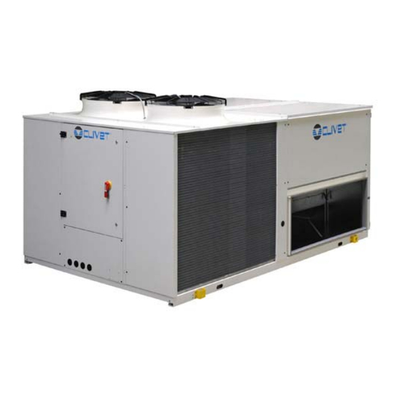
- Page 1 Installation and operating manual CSNX-XHE2 12.2-44.4 “Roof Top” air cooled heat pump for crowded room M07X40A16-00 22-03-16...
- Page 2 Yours faithfully. CLIVET Spa The data contained in this manual is not binding and may be changed by the manufacturer without prior notice. Reproduction, even is part, is FORBIDDEN © Copyright - CLIVET S.p.A. - Feltre (BL) - Italia...
-
Page 3: Table Of Contents
Index of contents General description Reception Positioning Water connections Aeraulic connections Electrical connections Start-up Control Maintenance Accessories Decommissioning Residual risks Technical information Dimensional drawings M07X40A16-00 CSNX-XHE2 12.2-44.4... -
Page 4: General Description
Disable the unit immediately in case of breakdown or malfunction. Contact a certified service agent. Use original spares parts only. Using the unit in case of breakdown or malfunction: voids the warranty it may compromise the safety of the unit may increase time and repair costs CSNX-XHE2 12.2-44.4 M07X40A16-00... - Page 5 Must be quoted when ordering spare parts. 1.14 Assistance request Note data from the serial number label and write them in the chart on side, so you will find them easily when needed. Series Size Serial number Year of manufacture Electrical wiringdiagram M07X40A16-00 CSNX-XHE2 12.2-44.4...
-
Page 6: Reception
Align the barycenter to the lifting point Use all the lifting brackets (see the dimensional section) Gradually bring the lifting belts under tension, making sure they are positioned correctly. 10. Before starting the handling, make sure that the unit is stable. CSNX-XHE2 12.2-44.4 M07X40A16-00... - Page 7 Keep packing material out of children’s reach it may be dangerous. Recycle and dispose of the packaging material in conformity with local regulations. Supports for handling: remove after the handling. Remove the coil protective mesh before the start-up M07X40A16-00 CSNX-XHE2 12.2-44.4...
-
Page 8: Positioning
Ignoring the previous indications could: reduce energy efficiency alarm lockout due to HIGH PRESSURE (in summer) or LOW PRESSURE (in winter) CSNX-XHE2 12.2-44.4 M07X40A16-00... - Page 9 When a heat pump is running it produces a considerable amount of water due to the defrosting cycles of the external coil. The condensate must be disposed in order to avoid damages to people and things. 3.5 CCK, CCKP configuration 3.6 Gas heating module - Electronic filters For details see: 10 Accessories p. 33 M07X40A16-00 CSNX-XHE2 12.2-44.4...
-
Page 10: Water Connections
The use of an anti-freeze solution results in an increase in pressure drop. Make sure that the glycol type utilized is inhibited (not corrosive) and compatible with the water circuit components. Do not use different glicol mixture (i.e. ethylene with propylene). 4.4 Humidifier For details see: 10 Accessories p. 33 CSNX-XHE2 12.2-44.4 M07X40A16-00... -
Page 11: Aeraulic Connections
Thermally isolate the channels and the flanges to avoid energy losses and forming of condensation. M07X40A16-00 CSNX-XHE2 12.2-44.4... -
Page 12: Electrical Connections
Guarantee the continuity of the screen during the entire extension of the cable. Respect impendency, capacity and attenuation indications. 6.4 Power input Fix the cables: if vacated may be subject to tearing. The cable must not touch the compressor and the refrigerant piping (they reach high temparatures). CSNX-XHE2 12.2-44.4 M07X40A16-00... - Page 13 Summer - winter mode remote change enabled by SA5* enabled by thermostat enabled by BMS automatic * Fan-only function not available function Fan only P263 disabled enabled by BMS enabled by SA5* *SUMMER - WINTER change mode by SA5 not available M07X40A16-00 CSNX-XHE2 12.2-44.4...
- Page 14 6.7 Wall mounted electronic room control CSNX-XHE2 12.2-44.4 M07X40A16-00...
- Page 15 The cable must have insulation features and non-flame propagation in accordance with applicable regulations. The RS485 serial line must be kept as far away as possible from sources of electromagnetic interference. Unit Metal septums Metal conduit Metal-lined sheath (sleeve) M07X40A16-00 CSNX-XHE2 12.2-44.4...
-
Page 16: Start-Up
12. measure super-heating and sub-cooling 13. check no anomalous vibrations are present 14. climatic curve personalization 15. climatic curve personalization 16. scheduling personalization 17. fire alarm configuration * 18. complete and available unit documentation * only if present CSNX-XHE2 12.2-44.4 M07X40A16-00... - Page 17 7.8 Voltages Check that the air and water temperatures are within in the operating limits. Start-up the unit. With unit operating in stable conditions, check: Voltage Total absorption of the unit Absorption of the single electric loads M07X40A16-00 CSNX-XHE2 12.2-44.4...
- Page 18 The air flow supply varies depending on the heat load, up to a minimum value compatible with the distribution system and the chosen air diffusion. The ventilation remains active even when the setpoint is fulfilled. Eco mode Variable airflow Standard mode Nominal Nominal Nominal 100% 100% 100% CSNX-XHE2 12.2-44.4 M07X40A16-00...
- Page 19 The set changes automatically according to the outside temperature. Even the operating mode changes automatically according to the outside temperature. The variation is defined by the climatic curve. P05 EnableAutoSet = 1 Setpoint 28°C COOL 22°C 21°C 19°C 5°C 20°C 24°C 35°C example Outdoor temp. M07X40A16-00 CSNX-XHE2 12.2-44.4...
- Page 20 The unit cannot be used as smoke extractor. Any fire detection devices built-in the unit must be considered as an auxiliary safety system, and, accordingly, must not be a replacement for any fire detection devices in the room. CSNX-XHE2 12.2-44.4 M07X40A16-00...
- Page 21 (for ex. Condensing circuit + direct expansion unit) Certification of setting in service: for all the units Periodical verifications: to be executed with the frequency indicated by the Manufacturer (see the “maintenance inspections” paragraph) M07X40A16-00 CSNX-XHE2 12.2-44.4...
-
Page 22: Control
8 - CONTROL SETPOINT ambient temperature DISPLAY MEANING KEY FUNCTION ON-OFF MODE CLOCK UP-DOWN... - Page 23 8 - CONTROL ON / OFF DAY MODIFICATION CLOCK mode °c 20.3 clock 10:00 mode 10:00 MODE CHANGE PARAMETERS mode °c 20.3 10:00 On/Off + Fan Code = 2 AUTO mode °c 20.3 10:00 BUTTON LOCK / UNLOCK mode °c 22.5 10:00 mode...
- Page 24 TIME BAND SCHEDULING mode 20.0 mode - - - - --:-- point 05 mode mode Time band mode point 04 mode mode °c 20.3 10:00 mode mode Time Time band band mode mode - - - - --:-- mode mode...
- Page 25 ALARMS STORED ALARM (installer use only) mode °c 20.3 10:00 mode CODE mode ALARM RESET S ALM SALM mode °c 20.3 10:00 mode 21.0° S001 mode 21.0° S001 mode mode 21.0° S001 mode 21.0° hhmm S001...
- Page 26 LIST OF ALARMS LIST OF ALARMS Stor CODE Description Stor CODE Description...
- Page 27 STATA Code = 1...
-
Page 28: Maintenance
* Refer to the local regulations; and ensure correct adherance. Companies and technicians that effect interventions of installation, maintenance/re- pairs, leak control and recovery must be CERTIFIED as expected by the local regulations. The leak control must be effected with annual renewal. CSNX-XHE2 12.2-44.4 M07X40A16-00... - Page 29 Verify that the aluminum fins are not bent or damaged, in the event of damages contact the authorized assistance center and get the fins straightened in order to restore the initial condition for an optimal air flow. M07X40A16-00 CSNX-XHE2 12.2-44.4...
- Page 30 Once cleaning is completed, pour water inside the bowl to check the regular outflow. 9.9 Compressor supply line shut-off valve A. Supply line shut-off valve Do not remove the seal Remove only if authorized by the manufacturer. Please contact the maker for informations. 9.10 crankcase heather Check: closure Operation CSNX-XHE2 12.2-44.4 M07X40A16-00...
- Page 31 Insert it back in its seat Remount the closing panels Old filters, washing wastewater and residues must be disposed of according to the current standards. 9.14 High efficiency air filter For details see: 10 Accessories p. 33 9.15 Humidifier For details see: 10 Accessories p. 33 M07X40A16-00 CSNX-XHE2 12.2-44.4...
- Page 32 9.16 Wall mounted electronic room control In the maintenance operations the keypad can be detached from the fixing support and directly connected to the unit electrical panel. CSNX-XHE2 12.2-44.4 M07X40A16-00...
-
Page 33: Accessories
10. Remount the evaporating heaters. ATTENTION: The evaporating heaters have a pre-set position to respect the air and water direction, that must be in counter-current. The incorrect position jeopardises the good operation and can cause flowing of the water downstream 11. Upon dehumidifier re-start, check operation again M07X40A16-00 CSNX-XHE2 12.2-44.4... - Page 34 The power supply bowl, piping: check they are free and without impurities Cylinder: 5 years not over 10000 hours of work (inspectional cylinders) replacement CSNX-XHE2 12.2-44.4 M07X40A16-00...
- Page 35 M07X40A16-00 CSNX-XHE2 12.2-44.4...
- Page 36 (wood, coal, gasoline, etc.) MATERIALS NECESSARY FOR MAINTENANCE Plastic or steel tank (750x750x310 mm) with settling bottom Acid detergent B01212 (code CLIVET C6460316) Protective gloves and goggles Graduated jug Pump for manual or pneumatic spraying Do not use aluminum tanks or galvanized Foresee a stainless steel frame that keeps the filters lifted from the tank base to have a settling bottom for the muds.
- Page 37 Delicately remove the filter avoiding dirtying the area below Insert the new filters, with the pockets vertically Close the panel Dispose of the old filters sending them to specialised recycling or collection centres (keep to the standards in force) M07X40A16-00 CSNX-XHE2 12.2-44.4...
- Page 38 All the control and safety devices GAS COCK GAS FILTER (LARGE SECTION) ANTI-VIBRATION JOINT GAS FILTER (SMALL SECTION) SAFET GAS SOLENOID VLAVE PRESSURE STABILISER MAIN GAS BURNER SOLENOID VALVE PILOT BURNER GAS SOLENOID VALVE CSNX-XHE2 12.2-44.4 M07X40A16-00...
- Page 39 M07X40A16-00 CSNX-XHE2 12.2-44.4...
-
Page 40: Decommissioning
The user must not dispose of the unit at the end of its life cycle as urban waste, it must instead be handed over to appropriate collection centres as set forth by current standards or as instructed by the distributor. CSNX-XHE2 12.2-44.4 M07X40A16-00... -
Page 41: Residual Risks
Do not remain in the vicinity of the safety valve and never leave the refriger- ating system taps closed. M07X40A16-00 CSNX-XHE2 12.2-44.4... - Page 42 STANDARD AIRFLOW General technical data Size 12.2 15.2 16.4 20.4 24.4 33.4 40.4 44.4 Cooling Cooling capacity 41,8 51,9 66,3 77,9 95,4 120,3 142,5 155,7 Sensible capacity 25,8 34,5 45,4 50,2 62,7 82,4 98,4 108,5 Compressor power input 12,2 15,5 19,3 22,5 27,4...
- Page 43 Size 12.2 15.2 16.4 20.4 24.4 33.4 40.4 44.4 Connections Condensate drain Power supply Standard power supply 400/3/50 400/3/50 400/3/50 400/3/50 400/3/50 400/3/50 400/3/50 400/3/50 CCK = return with fan and mixing chamber CCKP = return with fan and chamber with THOR thermodynamic recovery Performances in cooling: Indoor air temp.
- Page 44 Operating range (Cooling) The limits are meant as a guide. Please note that they have been calculated by considering: • general and non specific sizes • standard airflow • Non-critical positioning and correct use of the unit • operation at full load To verify the operating range of the operating units with percentages of fresh air, always calculate the Tm mixing temperature at the internal heat exchanger input.
- Page 45 Dimensional drawings Size 12.2 - 15.2 - CCK and CCKP configuration...
- Page 46 Size 12.2 - 15.2 Combustion module - CCK and CCPK configuration...
- Page 47 Size 16.4 - 20.4 - 24.4 - CCK and CCKP configuration...
- Page 48 Size 16.4 - 20.4 - 24.4 Combustion module - CCK and CCKP configuration...
- Page 49 Size 33.4-40.4-44.4 - CCK and CCKP configuration...
- Page 50 Size 33.4-40.4-44.4 Combustion module - CCK and CCKP configuration Single chamber...
- Page 51 Size 33.4-40.4-44.4 Combustion module - CAK and CBK configuration Double chamber...
- Page 52 Tel. +34 91 6658280 - Fax +34 91 6657806 - info@clivet.es CLIVET GmbH Hummelsbütteler Steindamm 84, 22851 Norderstedt - Germany Tel. + 49 (0) 40 32 59 57-0 - Fax + 49 (0) 40 32 59 57-194 - info.de@clivet.com CLIVET RUSSIA Elektrozavodskaya st. 24, office 509 - 107023, Moscow, Russia Tel.
Need help?
Do you have a question about the CSNX-XHE2 12.2-44.4 and is the answer not in the manual?
Questions and answers