Table of Contents
Advertisement
Quick Links
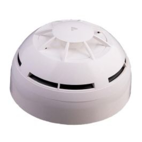
S2000
CONVENTIONAL PHOTO & CLASS A1R HEAT DETECTOR
GENERAL DESCRIPTION
This type of detector continuously samples the air and the temperature variation in the protected area to provide the earliest warning
of fire and yet offers a high level of false alarm rejection. This device benefits from a "Double Dust Trap" incorporated into the design
of the smoke entry ports, hence limiting potential contamination and extending periods between maintenance without compromising
sensitivity of response. These detectors are designed for open area protection and must only be connected to conventional control
panels. The centrally positioned red LED indicator provides 360° visibility and thus does not require any orientation during installation.
An in-built magnet test allows easy activation to verify correct functioning of the detectors on site.
IMPORTANT INSTALLATION WARNINGS
CONFIRM YOUR SYSTEM'S COMPATIBILITY BY CONSULTING WITH YOUR SUPPLIER OR WITH THE CONTROL PANEL'S
MANUFACTURER.
FOR SPECIFIC INFORMATION REGARDING DETECTOR AND DEVICE'S SPACING, PLACEMENT AND SPECIAL APPLICA-
TIONS REFER TO YOUR SPECIFIC NATIONAL OR INTERNATIONAL STANDARD CODES OF PRACTICE.
BEFORE INSTALLATION ENSURE THAT POWER IS REMOVED FROM THE SYSTEM.
DURING DEVICE'S CABLING, REMEMBER THAT CONNECTIONS TO THE TERMINALS ARE POLARITY SENSITIVE: SO,
PLEASE, CHECK THEM BY REFERRING TO THE WIRING INFORMATION GIVEN IN THIS MANUAL.
REMEMBER THAT THE ALARM CURRENT ABSORBED BY THE SENSOR MUST BE LIMITED IN ORDER TO AVOID PERMA-
NENT DAMAGE (SEE THE FOLLOWING PARAGRAPHS).
ADAPTOR BASE INSTALLATION
In order to fix a sensor to the wall it is necessary to use its adequate adaptor base. So:
1) select the position where you want to install the sensor and the base.
2) Install the base in the selected position by inserting the screws in the points indicated in picture 1.
Picture 1 - Wall fixing screw entry
points on the adaptor base.
LIMITATION OF THE ALARM CURRENT
When alarmed, the detector absorbs more current than usually does when quiescent: the absorbed current by the sensor in this state
is indicated as "alarm current"; since:
IF THE ALARM CURRENT EXCEEDS THE MAXIMUM SPECIFIED VALUE (SEE THE TECHNICAL SPECIFICATIONS TABLE),
THE DETECTOR CAN BE PARMANENTLY DAMAGED!
So, the alarm current must be limited in two different ways:
1) having a control panel which limits the alarm current through an in-built limiter.
2) By limiting the alarm current through a resistor fitted on the detector base (see the following wiring paragraphs).
If a remote LED indicator or another remote device is connected to the adaptor base and, so, the sensor, remember that:
ITS ABSORBED CURRENT WILL BE ADDED THE SENSOR'S ALARM CURRENT.
ARGUS SECURITY S.R.L. - Via Archimede 42, 20041, Agrate Brianza, Milano, Italy
TECHNICAL SPECIFICATIONS
Power supply
10 - 30 Vdc
Average standby current
90 uA @ 24 V
Maximum allowed alarm current
40 mA (externally limited)
Maximum allowed remote device
20 mA (externally limited)
current
Alarm temperature threshold
58 ° C
(class A1R)
-30 ° C / +70 ° C
Operating temperature range
(no condensation)
95% RH
Humidity
(no condensation)
Ingress protection rating
IP 21C
www.argussecurity.it
REMOTE OUTPUT CAPABILITY
Remote output capability is available as a standard feature so a remote indication lamp or a compatible platform sounder (check
power requirements) may be wired to the base terminals.
If other equipment is connected to the remote output, its supply current must be eventually limited by using an adequate
resistor. Consult the TECHNICAL SPECIFICATIONS table and assess the external device current absorption's value.
WIRING - BASE WITHOUT RESISTOR
This configuration is to be used only when the control panel limits the alarm current to less than the sensor's allowed maximum value
(picture 2).
LINE IN
LINE IN
POSITIVE (+)
NEGATIVE (-)
REMOTE INDICATOR
WARNINGS AND LIMITATIONS
Our devices use high quality electronic components and plastic materials that are highly resistant to
environmental deterioration. However, after 10 years of continuous operation, it is advisable to replace the
devices in order to minimize the risk of reduced performance caused by external factors. Ensure that this
device is only used with compatible control panels. Detection systems must be checked, serviced and
maintained on a regular basis to confirm correct operation.
Smoke sensors may respond differently to various kinds of smoke particles, thus application advice
should be sought for special risks. Sensors cannot respond correctly if barriers exist between them and
the fire location and may be affected by special environmental conditions.
Refer to and follow national codes of practice and other internationally recognized fire engineering stan-
dards.
Appropriate risk assessment should be carried out initially to determine correct design criteria and up-
dated periodically.
WARRANTY
All devices are supplied with the benefit of a limited 3 year warranty relating to faulty materials or manu-
facturing defects, effective from the production date indicated on each product.
This warranty is invalidated by mechanical or electrical damage caused in the field by incorrect handling
or usage.
Product must be returned via your authorized supplier for repair or replacement together with full informa-
tion on any problem identified.
Full details on our warranty and product's returns policy can be obtained upon request.
info@argussecurity.it
END OF LINE RESISTOR
LINE OUT
LINE OUT
NEGATIVE (-)
POSITIVE (+)
Picture 2 - Wiring
used when the
alarm current is
limited by the
control panel.
ARGUS SECURITY S.R.L.
Via Archimede, 42
20041, Agrate Brianza,
EN 54-7
Point type smoke detector
(optical)
EN 54-5
Point type heat detector
Class A1R
S2000
Technical data: see docu-
ment TDS-S2000 held by
the manufacturer.
L20-S2000-0001 (v1.0)
Milano
Italy
Advertisement
Table of Contents

Subscribe to Our Youtube Channel
Related Manuals for Argus Security S2000


Summary of Contents for Argus Security S2000
- Page 1 ITS ABSORBED CURRENT WILL BE ADDED THE SENSOR’S ALARM CURRENT. ment TDS-S2000 held by Full details on our warranty and product’s returns policy can be obtained upon request. the manufacturer. info@argussecurity.it L20-S2000-0001 (v1.0) ARGUS SECURITY S.R.L. - Via Archimede 42, 20041, Agrate Brianza, Milano, Italy www.argussecurity.it...
- Page 2 (picture 4). Picture 4 - The anti-tamper block and its handling. info@argussecurity.it L20-S2000-0001 (v1.0) ARGUS SECURITY S.R.L. - Via Archimede 42, 20041, Agrate Brianza, Milano, Italy www.argussecurity.it...
Need help?
Do you have a question about the S2000 and is the answer not in the manual?
Questions and answers