Advertisement
Quick Links
BI-DIRECTIONAL WIRELESS ADDRESSABLE MULTICRITERIA
DETECTOR WITH VARIABLE SENSITIVITY
OVERVIEW
This detector model samples the air and the environmental temperature in the protected area. An alarm condition is raised when the detected
environmental smoke quantity, the temperature level or the thermal variation rate exceeds the alarm threshold.
COMPATIBILITY
This detector is compatible only with wireless systems based on the Sagittarius protocol.
For more specific information concerning compatibility refer to your fire security system supplier.
INSTALLATION - IMPORTANT NOTES
For detector spacing, placement and special applications refer to your specific national standards.
Mount the detector as far as possible from metal objects, metal doors, metal window openings, etc. as well as cable conductors, cables
(especially from computers), otherwise the operating distance may greatly drop. The detector must NOT be installed near electronic devices
and computer equipment that can interfere with its wireless link quality.
This detector must be installed according precisely to the procedures described in this
manual.
Test this detector after installation.
BEFORE INSTALLING THE DETECTOR
1) Extract the batteries cover from the back of the detector.
2) Power-up the detector removing the isolating tab in the battery
housing. LED indicators signal "Power up".
3) Link the detector to the Sagittarius wireless system (LINKING).
4) Check the WIRELESS LINK QUALITY.
5) SELECT A GOOD LOCATION FOR THE DETECTOR.
6) Tag device's loop and address data (IDENTIFICATION).
7) Fix the detector supporting base to the wall (BASE INSTALLATION).
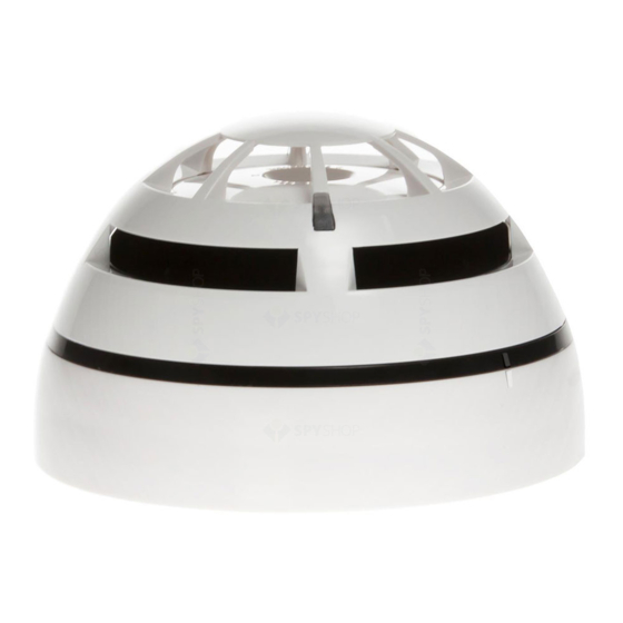
LED INDICATORS
Picture 1: provides visual indication for functional conditions and battery levels as indicated
in table 1.
Detector's status
LEDs indication
Power up
1 second GREEN, then 4 X 0.5 second RED blink
Linking to the system
Blinking GREEN until linking is completed
Link failure
RED on (continuous)
Normal condition
LEDs off
Alarm
Blinking RED: 0.5 second on and 0.5 second off
Battery 1 fault
0.1 second ORANGE blink, then 5 seconds off
Battery 2 fault
0.1 second GREEN blink, then 5 seconds off
0.1 second ORANGE, then 5 seconds off
Both batteries fault
0.1 second GREEN, then 5 seconds off
sequential ORANGE / GREEN 0.5 second blinking
Other fault
Tamper
LEDs off
Lost link with wire to
wireless translator /
LEDs off
wireless expander
Type 1 Test Mode
Blinking GREEN every 1 second for 1 minute
Type 2 Test Mode
GREEN on (continuous) for 30 minutes
ARGUS SECURITY S.R.L. - Via del Canneto, 14 - 34015 - Muggia (TS) - Italy
L-MC-SG
LED INDICATORS
Table 1
LINKING
The system is waiting to achieve a wireless child device (for further information
refer to the translator's or the Wirelex configuration software's literature):
1) Move the link switch's cursor from ON to the opposite side of its run (we will
call it BLANK, since it carries no indication). LED indicators signal "Linking to the
928m/02
system" (picture 2).
Linking is successful when:
a) the translator indicates so (check translator's literature)
b) the Wirelex software indicates so (check the Wirelex's literature).
If linking is unsuccessful:
2) Check if evident mistakes were made.
3) Perform the LINKING RECOVERY.
LINKING RECOVERY
1) Take out both batteries from their holders
2) Move alternatively the link switch to ON / BLANK five times (picture 2)
3) Move the link switch to ON
4) Reinsert both batteries into their holders, oriented as per polarity marks
5) Perform the LINKING procedure.
DETECTOR SENSITIVITY SETTINGS
During installation using the Wirelex software it's possible to set the smoke sensitivity and the heat class of the detector (see tables 4 and 5).
Otherwise if the installation is performed manually through the translator keyboard, default setting will be applied.
WIRELESS LINK QUALITY
It is possible to check wireless link quality between the detector and its linked-to translator or expander in this way:
1) Move the link switch to the ON position.
2) LED indicators will start blinking according to the following table:
Picture 1
Communication quality
No communication
Communication quality: 0 dB - 10 dB (Mark 2)
Communication quality: 10 dB - 20 dB (Mark 3)
Communication quality: 20 dB - 30 dB (Mark 4)
Communication quality: > 30 dB (Mark 5)
3) NOTE: Ensure the link switch is returned to the "BLANK" (operational) position on completion of testing.
SELECT A GOOD LOCATION FOR THE DETECTOR
Choose for the detector a placement position that:
- compliances with your specific standards
- is reached by a strong wireless signal from its linked-to
translator or expander module
- is not interfered by environmental factors.
IDENTIFICATION
For identification purposes, analogue loop number and device's
address can be recorded on the plastic tag supplied with the
base (picture 3).
Extract the plastic tag from the bottom of the base, write or label
identification data on it and, finally, insert it in the side slot of the
base.
www.argussecurity.it
info@argussecurity.it
Link switch
OR
Assessment
Fail
Poor, not acceptable
Medium-low, not recommended
Good
Excellent
Picture 2
During the linking phase, the
detector must be positioned
close to the aerial (within a
few centimeters) of the translator or
expander to which it is being linked.
Device's indication
Two red blinks
One red blink
One green blink
Two green blinks
Two green blinks
Table 2
Picture 3
L20-LMCXX-0001 (vA.7)
AB
Advertisement

Subscribe to Our Youtube Channel
Related Manuals for Argus Security L-MC-SG


Summary of Contents for Argus Security L-MC-SG
- Page 1 Type 2 Test Mode GREEN on (continuous) for 30 minutes base. Picture 3 Table 1 ARGUS SECURITY S.R.L. - Via del Canneto, 14 - 34015 - Muggia (TS) - Italy www.argussecurity.it info@argussecurity.it L20-LMCXX-0001 (vA.7)
- Page 2 During this procedure the linking switch must NOT SMOKE SENSITIVITY (EN 54) TEST MODES be touched at all ! Test modes make the L-MC-SG more reactive to aerosol stimulus; two test mode types are Threshold level Wirelex setting Notes provided: 1) Detach the detector from its base.
Need help?
Do you have a question about the L-MC-SG and is the answer not in the manual?
Questions and answers