Advertisement
Quick Links
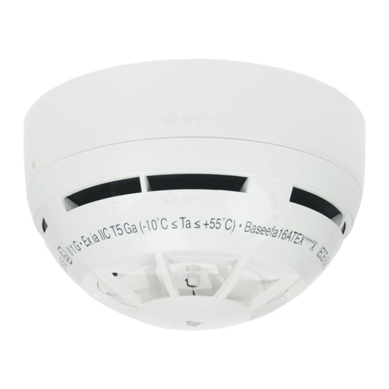
SG200
WIRELESS MULTI-CRITERIA DETECTOR
GENERAL DESCRIPTION
The wireless multi-criteria detector samples the air and temperature in the protected area to provide the earliest warning of fire and
yet offers a high level of false alarm rejection. An alarm condition is determined when:
a) the level of smoke inside the optical chamber exceeds the alarm threshold or
b) the level of temperature or the thermal variation versus time exceeds the alarm threshold;
consequently an alarm message is sent to the control panel through its wire to wireless translator module and, eventually, one or
more wireless expander modules.
The advanced design of the smoke inlet of the optical chamber guarantees a very high rejection to the introduction of dust, effectively
increasing the time between maintenance periods.
Communication between the detector and the translator / expander modules is wireless, via the „Sagittarius‟ bidirectional protocol.
PARTS OF THE PRODUCT
DETECTOR VISUAL LED INDICATOR
The wireless multi-criteria detector is equipped with a bicolour LED (red /
green) that provides visual indication for functional conditions and bat-
tery levels as indicated in table 1.
DEVICE'S POWER SUPPLY AND LINKING
The linking operation permits the configuration of the wireless multi-
criteria detector on the translator module.
The linking operation described below does not change if made directly
from the translator module or from the PC configuration program;
please, refer also to the "Guide to wireless system installation" and
similar documentation.
1) Verify that the secondary battery is present; if not, insert the battery
into its housing with the positive pole facing up (Picture 2).
2) Move the switch to position ON (Picture 3).
3) Insert the main battery (Picture 4).
Ensure that battery polarity is correct.
The visual LED indicator switches green once, then four times red
(programming mode) and will, successively, turn off. This
indicates that the detector is ready to be linked to the translator
module.
4) Move the switch in position 1 to trigger the communication between
the detector and the translator.
928m/01
1. Detector
2. Mounting base
3. Bicolour LED
4. Link - Program switch
5. Tamper switch
6. Batteries housing
7. Secondary battery
8. Main battery
9. Battery cover
Picture 1
Status description
LED indicator signal
Switching into "operating
mode"; occurs after main
4 short red LED blinks.
battery insertion.
Switching into "programming
mode"; occurs immediately
Green LED Short blinks.
after the linking phase is
started.
"Self-adjustment" mode;
occurs during the linking
Red LED blinking: 1 second
phase: device is programming
on and 0.1 second off.
itself with the wireless system
parameters.
Normal active mode or device
No signal from LED.
unpowered
Red LED blinking: 0.5 second
Alarm condition
on and 0.5 second off.
Orange blinking: 0.1 second
Main battery fault (low level)
on and 5 seconds off.
Secondary battery fault (low
Green LED blinking: 0.1
level)
second on and 5 seconds off.
Sequential orange-green LED
Both batteries fault
blinking: 0.1 second on and 5
seconds off.
Tamper fault
No signal from LED
Other fault type (fault on the
Sequential orange-green LED
optical analysis path, high
blinking: 0.5 second each
level of contamination inside
colour.
the optical chamber...)
Table 1
The green LED switches on once, then it blinks many times (operating mode), successively the red LED blinks many times (self-
adjustment mode) and, finally, after alternating green-red for one second, the indicator turns off: this indicates that the linking
procedure has been performed correctly and the detector has programmed itself .
The detector is linked and all the parameters (address, system code etc.) necessary to work correctly are stored.
If the LED remains switched on the red light it means that the linking operation failed. In this case remove the main
battery, switch alternatively the ON / 1 switch a few times in order to discharge the internal capacitor and then start again from
point 2).
IMPORTANT NOTE! Programming is considered to be completed successfully only if there is an indication of programming
success on the detector and on the translator or on the window of the PC configuration program.
5) Put on the battery cover.
Secondary battery housing
Picture 2 - Secondary battery housing
Picture 3 - Link - Program switch
COMMUNICATION QUALITY ASSESSMENT
It is possible to assess the wireless communication quality of the sensor by using a testing feature built in the device.
After a successful linking operation, by moving the Link-Programming switch on the ON position, the sensor‟s indicator will start
blinking according to table 2.
Communication quality
No connection
Link margin is less than 10 dB
Robust communication with link margin from 10 dB to 20 dB
Robust communication with link margin over 20 dB
Always remember to reposition the switch to 1 after the assessment operation: device will NOT work operatively
while the switch is on the ON position.
DETECTOR PLACEMENT
For specific information regarding detector spacing, placement and special applications refer to your specific national standards.
It is strongly advised to mount the device as far as possible from metal objects, metal doors, metal window openings, etc. as well as
cable conductors, cables (especially from computers), otherwise the operating distance
may greatly drop. The device should not be installed near electronic devices and com-
puter equipment that can interfere with the reception quality.
1) Select the position of the detector before installing and fixing its supporting base.
Verify, from that position, that the communication between the detector and
translator or the expander is correctly established and working (see the
COMMUNICATION QUALITY ASSESSMENT paragraph).
2) Install and fix the base, in the selected position, with the screws provided (Picture 5
and Picture 6).
3) Insert the detector onto the base (Picture 5).
Secondary battery
Main battery
Picture 4 - Main battery
Assessment
Device's indication
Fail
Two red blinks
Poor
One red blink
Good
One green blink
Excellent
Two green blinks
Picture 5 - Detector placement
SPNK-754431-117 (v2.2)
Table 2
Advertisement

Subscribe to Our Youtube Channel
Related Manuals for Argus Security SG200


Summary of Contents for Argus Security SG200
- Page 1 The green LED switches on once, then it blinks many times (operating mode), successively the red LED blinks many times (self- SG200 adjustment mode) and, finally, after alternating green-red for one second, the indicator turns off: this indicates that the linking procedure has been performed correctly and the detector has programmed itself .
- Page 2 * When a low battery condition is indicated, both, main and secondary, batteries must be changed altogether. RESET ** Check latest version of document TDS-SG200 for further data, obtainable from your supplier. To reset the detector from alarm or fault condition it is necessary to send the reset command from the control panel.
Need help?
Do you have a question about the SG200 and is the answer not in the manual?
Questions and answers