Table of Contents
Advertisement
Quick Links
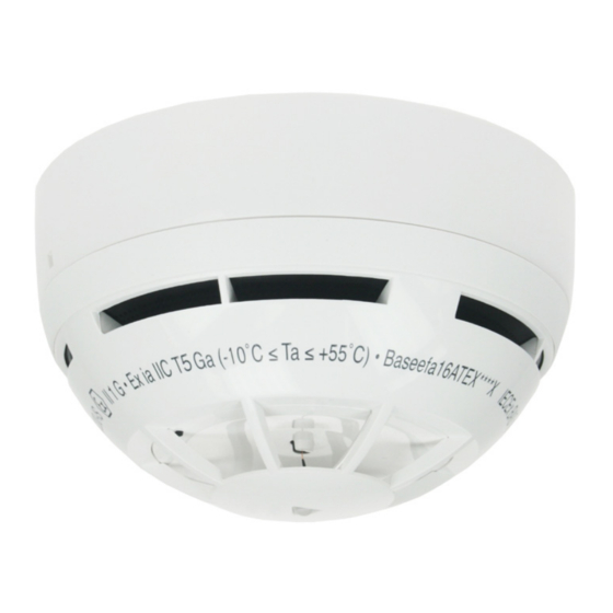
INTRODUCTION TO THE INTRINSICALLY SAFE FIRE DETECTION DEVICE
This wireless heat detector has been certified by Baseefa and has been awarded the ATEX Classification
≤ Ta ≤ +55˚C making it suitable for Category 1, 2 or 3 hazardous atmospheres with a maximum ambient temperature up to 55˚C.
The product has been assessed and certified for ATEX & IECEx requirements for hazardous applications according to the following standards:
IEC 60079-0:2011 / EN 60079-0:2012+A11:2013
IEC 60079-11:2011 / EN 60079-11:2012
IEC 60079-28:2015 / EN 60079-28:2015
It is recommended that installation only be carried out by qualified personnel
according to hazardous area safe working practice and in conformity to the terms
of the product certification. Note that the Translator Interface to which this device
will be linked does not form part of the ATEX/IECEx certified system and must be
sited in the safe area which is not subject to hazardous conditions.
GENERAL DESCRIPTION
The intrinsically safe wireless heat detector samples the air to determine an alarm
condition in the protected environment. Its design and construction makes it
suitable for installation in hazardous environment according to ATEX DIRECTIVE
2014/34/EU. System design should follow National Regulations or Codes of
Practice including reference to standards related to hazardous areas (e.g. EN
60079-14:2014) as appropriate.
These detection devices are designed for indoor applications and care should be
taken to ensure the environmental conditions are suited to the device type so that
unwanted alarm conditions are prevented.
DETECTOR VISUAL LED INDICATOR
The wireless heat detector is equipped with a LED that provides visual indication
for functional modes, battery faults and other fault types (see table 1).
LINKING THE DEVICE TO THE SYSTEM
Picture 2
Extract the isolating tab from
the back of the detector
ARGUS SECURITY S.R.L. - Via del Canneto, 14 - 34015 - Muggia (TS) - Italy
SG350-IS
INTRINSICALLY SAFE WIRELESS
HEAT DETECTOR
This detector must be
linked to the fire detec-
tion
system
installation; specifically it
must be linked to its
translator or expander
interface following the system design plan.
NOTE: As a safety precaution linking and power up of devices should
be carried out adjacent to the translator/expander interface in the safe
area.
For more detailed information about wireless linking refer to "Guide to
wireless system installation" document (APN-W0001) or refer to your system
supplier.
This manual gives the specific linking procedure applicable only to this detector.
LED SIGNAL MEANING
"Power up mode".
The isolating tab has just been
extracted or the main battery
has just been inserted.
"Linking mode".
Linking phase has been
started.
"Linking failure mode".
"Normal operating mode".
"Alarm mode".
Device unpowered.
Main battery fault (low charge)
Secondary battery fault (low
charge)
Both batteries fault
Tamper fault
before
Other fault type
Baseefa16ATEX0111X
IECEx BAS 16.0050X
II 1 G ; Ex ia IIC T5 Ga –10˚C
Picture 1
1. Detector
2. Mounting base
3. Visual LED indicator
4. Link switch
5. Tamper switch
6. Batteries housing
7. Secondary battery
8. Main battery
9. Battery cover
Table 1
LED VISUAL SIGNAL
Green LED blinks;
Orange LED on for 2 seconds;
Red LED blinks.
Green LED blinks;
Red LED blinking 1 second on
and 0.1 second off;
Green and red LED alternat-
ing for 1 second.
Red LED continuously on.
LED off.
Red LED blinking: 0.5 second
on and 0.5 second off.
LED off.
Orange blinking: 0.1 second
on and 5 seconds off.
Green LED blinking: 0.1
second on and 5 seconds off.
Sequential orange-green LED
blinking: 0.1 second on and 5
seconds off.
LED off.
Sequential orange-green LED
blinking: 0.5 second each
colour.
www.argussecurity.it
Advertisement
Table of Contents

Summary of Contents for Argus Security SG350-IS
- Page 1 For more detailed information about wireless linking refer to “Guide to wireless system installation” document (APN-W0001) or refer to your system supplier. This manual gives the specific linking procedure applicable only to this detector. ARGUS SECURITY S.R.L. - Via del Canneto, 14 - 34015 - Muggia (TS) - Italy www.argussecurity.it...
- Page 2 STANDARD LINKING PROCEDURE From the moment you switch on “1” to the moment linking comes to an end, the detector When the Wirelex program or the translator module is waiting for this device to be linked, perform must be only about 10cms the following actions: away from the translator or expander 1) Check that the link switch is on the “ON”...
- Page 3 4) Wipe the exterior housing of the detector with a clean, damp, lint-free cloth to remove any surface film that can later attract airborne contaminants 5) Install the detector onto its base again 6) Test the detector ARGUS SECURITY S.R.L. - Via del Canneto, 14 - 34015 - Muggia (TS) - Italy www.argussecurity.it...
- Page 4 However, after 10 years of continuous operation, it is advisable to replace the devices in order to minimize the risk of reduced performance caused by external factors. Ensure that this device is only used with ARGUS SECURITY S.R.L. compatible control panels. Detection systems must be checked, serviced and maintained on a regular basis to Via del Canneto, 14 confirm correct operation.


Need help?
Do you have a question about the SG350-IS and is the answer not in the manual?
Questions and answers