Table of Contents
Advertisement
Advertisement
Table of Contents

Related Manuals for iCarsoft CR MAX BT


Summary of Contents for iCarsoft CR MAX BT
- Page 1 CR MAX BT User Manual PROFESSIONAL . FAST . SMART . POWERFUL...
- Page 3 Trademarks iCarsoft, CR MAX BT is trademarks of iCarsoft Technology Inc, registered in the United States and other countries. All other marks are trademarks or registered trademarks of their respective holders. Copyright Information No part of this manual may be reproduced, stored in a retrieval system or transmitted, in any form or by any means, electronic, mechanical, photocopying, recording, or otherwise without the prior written permission of iCarsoft.
- Page 4 Safety Instructions The safety messages herein cover situations iCarsoft is aware of. iCarsoft cannot know, evaluate or advise you as to all of the possible hazards. You must be certain that any condition or service procedure encountered does not jeopardize your personal safety.
-
Page 5: Table Of Contents
1 Using this Manual ......................1 1.1 Conventions ......................1 2 General Introduction ......................1 2.1 CR MAX BT Display Tablet..................2 2.2 CR MAX BT VCI Device ................... 4 2.3 Accessory Kit ......................8 3 Getting Started ........................ 10 3.1 Powering Up ......................10 3.2 Powering Down ..................... - Page 6 6.2 Play Back ....................... 35 6.3 User Manual ......................37 6.4 Training ........................37 6.5 Report........................37 6.6 Data Link Connector (DLC) Location ..............37 7 Upgrade ..........................37 8 Shop Information ......................39 8.1 Workshop Info ....................... 40 8.2 Customer Info ......................40 8.3 Vehicle History .......................
-
Page 7: Using This Manual
1024 x 600 quality. Together with the ability to quickly read and clear DTCs for all available modules of the majority of the makes and models on the market, CR MAX BT provides you with superior special functions, including OIL (Oil Reset Service), EPB... -
Page 8: Cr Max Bt Display Tablet
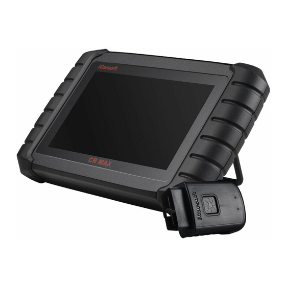
2.1.1 Functional Description Figure 2-1 Display Tablet Front View 7.0” LCD Capacitive Touchscreen. Figure 2-2 CR MAX BT Display Tablet Back View Collapsible Stand – extends from the back to allow hands-free viewing of the Display Tablet. Heat Sink or Speaker. - Page 9 Figure 2-3 CR MAX BT Display Tablet Top View Mini USB Port. USB Port –For connection of adapters, computers or VCI, etc. Lock/Power Button – long press button to turn tablet off and on. Quick press button to lock screen.
-
Page 10: Cr Max Bt Vci Device
Honda Diag-H Protocol, TP2.0, TP1.6. 2.2 CR MAX BT VCI Device The wireless diagnostic interface CR MAX BT VCI is a small vehicle communication interface(VCI) used to connect to a vehicle's diagnostic connector(DLC) and connect with the Tablet, as a vehicle communication interface(VCI) for vehicle data transmission. - Page 11 Vehicle data connector (16-pin)-connects VCI directly to the vehicle's 16-pin diagnostic interface (DLC). Mini USB Port - The CR MAX BT can be connected to the VCI through a USB cable. Power indicator: red - When the VCI is connected to a power source, connected to a vehicle, or bound to a device, this indicator light is always bright red.
- Page 12 Communication BT5.0 dual mode Wireless frequency 2.4 GHz Input voltage range 9V DC -- 18V DC Power supply current 100mA@12 V Operating temp. 0° C to 50° C(32° F to 122° F) Storage temp. -20° C to 70° C(-4° F to 158° F) Dimensions (L * W * H) 94 mm (3.7’’) * 56mm (2.2’’) * 28 mm (1.1’’) Weight...
- Page 13 Figure 2-6 VCI Device binding screen 2 After Bluetooth is connected, wait for the device to be searched, and tap the tablet with the same serial number as the VCI device to bind. Figure 2-7 VCI Device binding screen 3 After the binding is successful, the page will display a successful signal and display the serial number of the VCI device.
-
Page 14: Accessory Kit
Figure 2-8 VCI Device binding screen 4 If you need to unbind, tap the unbind button in the lower right corner, and the device will be unbound, and you can re-bind with other VCI devices. If the binding is successful, the VCI binding option on the setting page will display the serial number of the bound VCI device. - Page 15 (DLC) of the vehicle through the VCI Extended Cable, Transfer vehicle data to CR MAX BT tablet. Figure 2-12 VCI adapter 2.3.2 Other Accessories Mini USB Cable Connects the Display Tablet to the PC or DC external power adapter.
-
Page 16: Getting Started
Press the Lock/Power button on the top right side of the tablet to power the unit on. The system boots up, and displays the lock screen. Slide the lock icon up and down to access the CR MAX BT job menu. - Page 17 Detailed descriptions of the menu structures are found in the chapters for each application. 3.1.1 Application Buttons The tablet below briefly describes each of the applications in the CR MAX BT system. Table 3-1 Applications Button...
- Page 18 Code Operations on chapter 11. Feedback and get on-line service from iCarsoft with Support the CR MAX BT tablet. See Support Operations on chapter 12. Manage the application and database installed on the CR MAX BT tablet. See Uninstall Operations on Uninstall chapter 13.
-
Page 19: Powering Down
Screenshot the displayed information. CR MAX BT Home Returns to CR MAX BT Job Menu. 3.2 Powering Down All vehicle communications must be terminated before shutting down the Display Tablet. Forcing a shutdown while the tablet is communicating may lead to ECM problems on some vehicles. -
Page 20: Getting Started
4.1.1 Vehicle Menu Layout When the tablet is properly connected to the vehicle, the platform is ready to start vehicle diagnosis. Tap on the Diagnostics application button on the CR MAX BT Job Menu, the Vehicle Menu then displays. Figure 4-1 Sample Vehicle Menu... -
Page 21: Vehicle Identification
Vehicle select 4.2.1 Auto Identify The CR MAX BT diagnostic system features the latest VIN-based Auto VIN Scan function to identify vehicles with just one touch, enabling the technician to quickly identify the vehicle, scan all the diagnosable ECUs on the vehicle and perform diagnostics on the selected system. - Page 22 Figure 4-3 Sample Vehicle information Screen Manual VIN Input For some vehicles that not supporting the Auto VIN Scan function, the CR MAX BT diagnostic system allows you to enter the vehicle VIN manually. To perform Manual VIN Input Tap the Diagnostics application button from the CR MAX BT Job Menu.
-
Page 23: Navigation
To perform Vehicle Select Tap the Diagnostics application button from the CR MAX BT Job Menu. The Vehicle Menu displays. Tap the vehicle brand of the test vehicle. - Page 24 Status Information Bar The Status Information Bar at the top of the Main Section displays the following items: 1) Back button – Returns to the CR MAX BT Job Menu. 2) Menu Title – displays the menu heading of the Main Section.
-
Page 25: Diagnosis Mode
This type of messages displays a warning that a selected action may result in an irreversible change or loss of data. The typical example of this is the “Erase Codes” message. Error Messages Error messages display when a system or procedural error has occurred. Examples of possible errors include a disconnection or communication interruption. -
Page 26: Diagnostic Operation
Right side – Show vehicle control unit status. Fault | (2) : Indicates that the fault code is detected; 2 represents the number of faults detected. Pass : Indicates that the vehicle is equipped with this system and has no fault code. - Page 27 the program will guide you to the diagnostic function menu after selections are made. Figure 4-7 Sample Diagnostic Operation Screen The Function Menu options vary slightly for different vehicles. The function menu may include: Module Information – Read full electronic system module information, such as VIN, part number, version, supplier, production date of ECU.
- Page 28 including unit type, version numbers and other specifications. Also you can save these data by press save button. The sample Module Information screen displays as below: Read Fault Codes This function retrieves and displays the DTCs from the vehicle’s control system. The Read Codes screen varies for each vehicle being tested.
- Page 29 Figure 4-8 Sample View Data Screen Main Section Name Column – displays the parameter names. Check Box – tap the check box on the left side of the parameter name to make item selection. Tap the check box again to de-select the item. Drop-down Button –...
- Page 30 Reading of status parameters, such as a switch reading, which are mostly in word form, such as ON, OFF, ACTIVE, and ABORT, can only be displayed in Text Mode. Whereas reading of value parameters, such as a sensor reading, can be displayed in text mode and other graph modes.
-
Page 31: Generic Obdii Operations
4.6.1 General Procedure To access the OBDII/EOBD diagnostics functions Tap the Diagnostics application button from the CR MAX BT Job Menu. The Vehicle Menu displays. Tap the OBD button. The device will automatically establish communication with the vehicle.When the communication is complete, vehicle protocol information will be displayed. - Page 32 NOTE ○ Tapping button beside the function name to display additional function information. Select a function option to continue. Read Codes Erase Codes I/M Readiness Live Data Freeze Frame Vehicle Information O2 Monitor Test ...
-
Page 33: Exiting Diagnostics
erased. This Drive Cycle – displays the status of monitors since the beginning of the current drive cycle. Live Data This function displays the real time PID data from ECU. Displayed data includes analog inputs and outputs, digital inputs and outputs, and system status information broadcast on the vehicle data stream. -
Page 34: Service Operations
CR MAX BT Job Menu. Once the Diagnostics application is no longer communicating with the vehicle, it is safe to open other CR MAX BT applications, or exit the CR MAX BT Diagnostic System and return to the Android System’s Home screen. -
Page 35: Abs Bleeding (Bld) Service
Figure 5-1 Sample Service Function List After entering each special function, the screen will display the Vehicle Manufacturer, you need to make a step-by-step selection according to your test vehicle. 5.1 ABS Bleeding (BLD) Service When the ABS contains air, or the ABS computer / ABS pump / brake master cylinder / brake cylinder/ brake fluid is replaced, the ABS bleeding function must be performed to bleed the brake system to restore ABS brake sensitivity. -
Page 36: Electronic Throttle Control (Etc) Service
Accident repairs where damage to the steering angle sensor or assembly, or any part of the steering system may have occurred. NOTE 1) iCarsoft accepts no responsibility for any accident or injury arising from servicing the SAS system. When interpreting DTCs retrieved from the vehicle, always follow the manufacturer’s recommendation for repair. -
Page 37: Battery Management System (Bms)
each vehicle being tested. Observe the menu titles and on-screen instructions to make correct option selections. 3) Before starting the procedure, make sure the vehicle has an ESC button. Look for the button on dash. Steering Column Calibration If the steering column or instrument cluster is replaced or the instrument cluster software is updated, a body system steering column calibration is required. -
Page 38: Head Lamp
The ECM monitors driving style and selects a suitable time to employ regeneration. Cars driven primarily at idling speed and low load will attempt to regenerate earlier than cars driven with higher loads and at higher speed. For regeneration to occur, a prolonged high exhaust temperature must be obtained. -
Page 39: Gearbox Reset
inputting TPMS sensor replacement IDs and testing sensors. Select tire pressure sensor replacement (Front right wheel sensor) as an example. NOTE This function will require the sensor ID be inputted on the screen. The sensor IDs can be read directly from the sensor or by using a sensor activation tool that can read the ID. -
Page 40: Fuel Pump
and matching functions need to be performed to make the air filter work normally. 5.15 Fuel Pump After the fuel pump is disassembled, repaired or replaced, it may cause the fuel pump to be unable to continuously provide fuel to the fuel injection nozzle. At this time, the function needs to be executed to activate the replaced fuel pump so that the car can start to inject fuel normally and make the engine achieve the ideal Running status. -
Page 41: User Data
Different models will have different menu modes. This manual is for reference. Everything in kind shall prevail. If there is any increase or decrease in the function of the product, the actual product shall prevail. User Data The User Data application is used to store and view saved files. Contains images, play back, user manual, Training, Report, DLC Location. - Page 42 Figure 6-2 Sample Play Back Screen 2 3. Select the check box in the lower right corner of each list, tap the button in the upper right corner to execute PDF output function or delete. Figure 6-3 Sample Play Back Screen 3 Perform PDF output function:...
-
Page 43: User Manual
PDF report in "Report". Figure 6-4 Sample Play Back Screen 6 6.3 User Manual The user manual section provides users to view the CR MAX BT user manual, quick operation guide, how to create a report, how to perform feedback, etc. 6.4 Training The training section provides videos of operating applications to facilitate customers to quickly understand the operating functions of CR MAX BT. - Page 44 Any updates that are found can be downloaded and installed on the device. This section describes installing an update to the CR MAX BT System. Figure 7-1 Sample Update Screen – for CR MAX BT ①...
-
Page 45: Shop Information
1. Make sure the Display Tablet is connected to a power source with stable access to the internet. 2. Tap the Upgrade application button from the CR MAX BT Job Menu; or tap the update notification message when received; or tap the Upgrade icon on Vehicle Menu in Diagnostics application. -
Page 46: Workshop Info
Modify edit and Tap this button to save the modified customer save information and vehicle information. Add Customer Tap this button to open a note form. New customer Notes notes can be added. 8.1 Workshop Info Use the Workshop Information form to edit, input and save the detailed workshop information, such as shop name, address, phone number and other remarks, which when printing vehicle diagnostic reports and other associated test file, will display as the header of the printed documents. -
Page 47: Vehicle History
Figure 8-1 Sample Customer Info Sheet 1 3. Tap on the input field that needs to be altered or supplemented, and enter updated information. 4. Tap the Modify edit and save button on the top toolbar to save the updated information, or tap the Back button on the top toolbar to exit without saving. -
Page 48: Settings
The vehicle’s Diagnostics screen displays a new diagnostic session. Settings Selecting Settings application opens a setup screen to adjust the default setting and view information about the CR MAX BT system. There are ten system settings: VCI Binding ... -
Page 49: Vci Binding
Metric or Imperial. A check mark will display on the right of the selected unit. 9.3 Language This option allows you to adjust the display language of the CR MAX BT application, which is available in several languages. 9.4 Data log This option allows you to access the diagnostic system log. -
Page 50: Restore Factory Settings
Slide up and down to select the required model and code. To access fault code 1. Tap the Fault Code application on the CR MAX BT Job Menu. 2. Slide up and down to select the required model and code. 3. Tap the lookup button in the upper right corner, and the query results will be displayed in the box below. -
Page 51: Uninstall
3 photos to submit together. Uninstall This section allows you to manage the software applications installed on the CR MAX BT Diagnostics System. Select this section to open a management screen, on which you can check all the available vehicle diagnostic applications. -
Page 52: About
About The About screen lists the CR MAX BT’s version, hardware, and serial number, storage and etc.. Maintenance and Service 16.1 Maintenance Instructions The following shows how to maintain your devices, together with precautions to take. Use a soft cloth and alcohol or a mild window cleaner to clean the touch screen on the tablet. -
Page 53: About Battery Usage
Your device may have not been connected to the charger properly. Check the connector. NOTE If your problems persist, please contact iCarsoft’s technical support personnel or your local selling agent. 16.3 About Battery Usage Your tablet is powered by a built-in Lithium-ion Polymer battery. This means that, unlike other forms of battery technology, you can recharge your battery while some charge remains without reducing your tablet’s autonomy due to the “battery memory effect”... -
Page 54: Compliance Information
Email: support@icarsoft.com 16.4.2 Repair Service If it becomes necessary to return your device for repair, please download the repair service form from www.iCarsoft.com, and fill it in. The following information must be included: Contact name Return address ... - Page 55 WARNING Changes or modifications not expressly approved by the party responsible for compliance could void the user’s authority to operate the equipment. NOTE This equipment has been tested and found to comply with the limits for a Class B digital device, pursuant to Part 15 of the FCC Rules.
-
Page 56: Warranty
Technology Inc. (the Company) warrants to the original retail purchaser of this CR MAX BT Diagnostic Device, that should this product or any part thereof during normal consumer usage and conditions, be proven defective in material or workmanship that results in product failure within one (1) year period from the date of purchase, such defect(s) will be repaired, or replaced (with new or rebuilt parts) with Proof of Purchase, at the Company’s... - Page 57 Technology Inc. www.icarsoft.us www.icarsoft.com All Rights Reserved...
Need help?
Do you have a question about the CR MAX BT and is the answer not in the manual?
Questions and answers
Can I use icarsoft CR max Bt to diagnostic a truck ?