Table of Contents
Advertisement
Quick Links
Trademarks
iCarsoft, CR Max and CR MAX BT are trademarks of iCarsoft
Intelligent Technology Corp., Ltd., registered in the United States
and other countries. All other marks are trademarks or registered
trademarks of their respective holders.
Copyright Information
No part of this manual may be reproduced, stored in a retrieval
system or transmitted, in any form or by any means, electronic,
mechanical, photocopying, recording, or otherwise without the prior
written permission of iCarsoft.
Disclaimer of Warranties and Limitation of Liabilities
All information, specifications and illustrations in this manual are
based on the latest information available at the time of printing.
iCarsoft reserves the right to make changes at any time without
notice. While information of this manual has been carefully checked
for accuracy, no guarantee is given for the completeness and
correctness of the contents, including but not limited to the product
specifications, functions, and illustrations.
iCarsoft will not be liable for any direct, special, incidental, indirect
damages or any economic consequential damages (including the
loss of profits).
IMPORTANT
Before operating or maintaining this unit, please read this manual
carefully, paying extra attention to the safety warnings and
precautions.
For Services and Support
Http://www.icarsoft.us
Http://www.icarsoft.com
Support@icarsoft.us
For technical assistance in all other markets, please contact your
local selling agent.
I
Advertisement
Table of Contents

Related Manuals for iCarsoft CR MAX


Summary of Contents for iCarsoft CR MAX
- Page 1 Trademarks iCarsoft, CR Max and CR MAX BT are trademarks of iCarsoft Intelligent Technology Corp., Ltd., registered in the United States and other countries. All other marks are trademarks or registered trademarks of their respective holders. Copyright Information No part of this manual may be reproduced, stored in a retrieval...
- Page 2 Safety Information For your own safety and the safety of others, and to prevent damage to the device and vehicles upon which it is used, it is important that the safety instructions presented throughout this manual be read and understood by all persons operating or coming into contact with the device.
- Page 3 Safety Instructions The safety messages herein cover situations iCarsoft is aware of. iCarsoft cannot know, evaluate or advise you as to all of the possible hazards. You must be certain that any condition or service procedure encountered does not jeopardize your personal safety.
- Page 4 Keep a fire extinguisher suitable for gasoline, chemical, and electrical fires nearby. Do not connect or disconnect any test equipment while the ignition is on or the engine is running. Keep the test equipment dry, clean, free from oil, water or ...
-
Page 5: Table Of Contents
ONVENTIONS 1.1.1 Bold Text ................1 1.1.2 Notes and Important Messages........1 1.1.3 Hyperlink ................2 1.1.4 Illustrations ................ 2 2 GENERAL INTRODUCTION ............3 ............... 3 CR MAX D ISPLAY ABLET 2.1.1 Functional Description ............3 2.1.2 Power Sources...............4 2.1.3 Technical Specifications............5... - Page 6 Making Selections ............... 20 4.3.3 .................. 21 IAGNOSIS 4.4.1 Smart Scan................21 4.4.2 Manual................23 ............29 4.5 G OBD II O ENERIC PERATIONS 4.5.1 General Procedure ............... 29 4.5.2 Function Descriptions ............31 ..............33 XITING IAGNOSTICS 5 SERVICE OPERATIONS ................ 34 ................
- Page 7 Image Files ................77 6.1.1 6.1.2 Play Back................78 6.1.3 User Manual............... 78 6.1.4 Training................79 6.1.5 FAQ ..................80 6.1.6 Data Link Connector(DLC) Location ........80 7 UPGRADE ..................81 8 SHOP INFORMATION.................84 ................. 84 ORKSHOP ................85 USTOMER 8.2.1 Customer Notes..............87 .................
- Page 8 16 MAINTENANCE AND SERVICE ............108 16.1 ............108 AINTENANCE NSTRUCTIONS 16.2 .............109 ROUBLESHOOTING HECKLIST 16.3 ............. 110 BOUT ATTERY SAGE 16.4 ..............111 ERVICE ROCEDURES 16.4.1 Technical Support ............111 16.4.2 Repair Service ............... 111 16.4.3 Other Services............... 112 17 COMPLIANCE INFORMATION ............113 18 WARRANTY..................116 18.1 ............116...
-
Page 9: Using This Manual
Using this Manual This manual contains device usage instructions. Some illustrations shown in this manual may contain modules and optional equipment that are not included in your system. Conventions The following conventions are used. 1.1.1 Bold Text Bold text is used to highlight selectable items such as buttons and menu options. -
Page 10: Hyperlink
IMPORTANT Keep the cable away from heat, oil, sharp edges and moving parts. Replace damaged cables immediately. 1.1.3 Hyperlink Hyperlinks, or links, that take you to other related articles, procedures, and illustrations are available in electronic documents. Blue italic text indicates a selectable hyperlink and blue underlined text indicates a website link or an email address link. -
Page 11: General Introduction
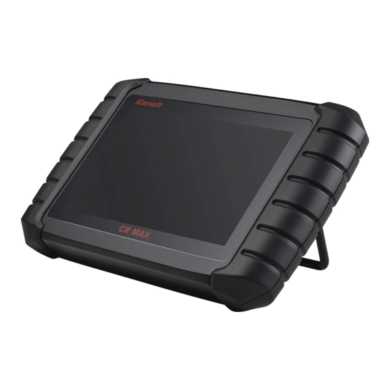
1024 x 600 quality. Together with the ability to quickly read and clear DTCs for all available modules of the majority of the makes and models on the market, CR MAX provides you with superior special functions, including Oil Reset, EPB... -
Page 12: Power Sources
Figure 2-2 CR MAX Display Tablet Back View 2. Collapsible Stand – extends from the back to allow hands-free viewing of the Display Tablet. 3. Heat Sink or Speaker Figure 2-3 CR MAX Display Tablet Top View 4. Mini USB OTG Port 5.USB Host (Wireless has this interface, wired does not have this... -
Page 13: Technical Specifications
Internal Battery Pack Vehicle Power External Power Supply Internal Battery Pack The Display Tablet can be powered with the internal rechargeable battery, which if fully charged can provide sufficient power for about 4.5 hours of continuous operation. Vehicle Power When the Display Tablet is connected to the test vehicle via the main cable, the Display Tablet automatically receives power from the... - Page 14 Mini USB 2.0 USB 2.0 Connectivity Wi-Fi Bluetooth OBD II Body Color Black Audio Input/ Input: N/A Output Output: Buzzer & Speaker OBD DLC Voltage Range:9-18V Power and 3.7V/5000mAh lithium-polymer battery Battery ...
-
Page 15: Accessory Kit
Accessory Kit 2.2.1 Main Cable The Main Cable connects the Display Tablet to the vehicle’s data link connector (DLC). Figure 2-4 Main Cable 2.2.2 Other Accessories Mini USB Cable Connects the Display Tablet to the PC or DC external power adapter. USB External Power Adapter Together with the mini USB cable, connects the Display Tablet to the external DC power port... -
Page 16: Getting Started
Press the Lock/Power button on the top right side of the tablet to power the unit on. The system boots up, and displays the lock screen. Slide the lock icon up and down to access the CR Max job menu. Figure 3-1 Sample CR MAX Job Menu 1. -
Page 17: Application Buttons
Accesses the organization system for User Data saved data files. User Data Operations on page 65. Checks for the latest update available for the CR MAX system, and performs Upgrade updates. See Upgrade Operations on page 69. Accesses workshop information service program,... -
Page 18: Locator And Navigation Buttons
Operations on page 88. Launches the Support platform which synchronizes iCarsoft’s on-line service Support base station with the CR MAX tablet. See Support Operations on page 89. Manage the firmware applications installed Uninstall on the CR MAX Diagnostics System. See Uninstall Operations on page 92. -
Page 19: Powering Down
Takes a screenshot when you want to Screenshot save the displayed information. CR MAX Home Returns to CR MAX Job Menu. Powering Down All vehicle communications must be terminated before shutting down the Display Tablet. A warning message displays if a shutdown is attempted while the tablet is communicating with the vehicle. -
Page 20: Reboot System
Tap OK, the tablet will turn off in a few seconds. 3.2.1 Reboot System In case of system crash, long press the Lock/Power button and tap Reboot option to restart the system. -
Page 21: Diagnostics
When the tablet is properly connected to the vehicle, the platform is ready to start vehicle diagnosis. Tap on the Diagnostics application button on the CR MAX Job Menu, the Vehicle Menu then displays. Figure 4-1 Sample Vehicle Menu 1. Top Toolbar Buttons 2. -
Page 22: Vehicle Identification
After establishing communication with the vehicle. Tap the desired manufacturer button to start a diagnostic session. Vehicle Identification The CR MAX diagnostic system supports four methods for Vehicle Identification. 1. Auto VIN Scan 2. Manual VIN Input... -
Page 23: Auto Vin Scan
4. Manual Selection 4.2.1 Auto VIN Scan The CR MAX diagnostic system features the latest VIN-based Auto VIN Scan function to identify vehicles with just one touch, enabling the technician to quickly identify the vehicle, san all the diagnosable ECUs on the vehicle and perform diagnostics on the selected system. -
Page 24: Manual Vin Input
Figure 4-3 Sample Auto VIN Screen 2 3. Review the information to ensure it is correct. Tap Yes to confirm the vehicle or NO if the information is not correct. Figure 4-4 Sample Vehicle Profile Screen 4. The tool will establish communication with the vehicle to read control unit information. -
Page 25: Smart Scan
For some vehicles that not supporting the Auto VIN Scan function, the CR MAX diagnostic system allows you to enter the vehicle VIN manually. To perform Manual VIN Input Tap the Diagnostics application button from the CR MAX Job Menu. The Vehicle Menu displays. -
Page 26: Manual Selection
Figure 4-7 Sample Selection Screen To perform Automatic Selection 1. Tap the Diagnostics application button from the CR MAX Job Menu. The Vehicle Menu displays. 2. Tap the vehicle brand of the test vehicle. 3. Tap Smart Scan and the system will proceed to acquire the VIN. -
Page 27: Navigation
The Status Information Bar at the top of the Main Section displays the following items: 1. Back button--- Returns to the CR MAX Job Menu. 2. Menu Title – displays the menu heading of the Main Section. 3. Voltage Icon – displays the vehicle’s voltage status. -
Page 28: Screen Messages
Functional Buttons The displayed Functional Buttons vary depending on the stage of operations. Functional buttons can be used to navigate menus, to save or clear diagnostic data, to exit scanning and to perform a number of other control functions. The use of these buttons will be discussed in detail in the following sections of the corresponding test operations. -
Page 29: Diagnosis
Diagnosis The Diagnostics application enables a data link to the electronic control system of the test vehicle for vehicle diagnosis. The application performs functional tests, retrieves vehicle diagnostic information such as trouble and event codes and live data for various vehicle control systems, such as engine, transmission, and ABS. - Page 30 Figure 4-9 Sample Auto Scan Operation Screen Enter Smart Scan, the system will scan your vehicle’s system for you. Figure 4-10 Sample Auto Scan Operation Screen Functional Buttons A brief description of the operations of the Smart Scan’s Functional Buttons’ are displayed in the table below. Table 4-3 Functional Buttons in Auto Scan...
-
Page 31: Manual
Name Description Back Returns to the previous screen or exits Auto Scan. 4.4.2 Manual This option allows you to manually locate a required control system for testing through a series of choices. Follow the menu driven procedures and make proper selection each time; the program will guide you to the diagnostic function menu after selections are made. - Page 32 Actuation Test -- Through this function can be sent to the car instructions, such as lifting Windows, lifting chair, and so on, these functions vary from model to model. To perform a diagnostic function Establish communication with the test vehicle. Identify the test vehicle by selecting from the menu options.
- Page 33 This function retrieves and displays the DTCs from the vehicle’s control system. The Read Codes screen varies for each vehicle being tested. On some vehicles, freeze frame data can also be retrieved for viewing. The sample Read Codes screen displays as below: Figure 4-13 Sample Read Fault Codes Screen Functional Button ...
- Page 34 function is completed. a) Tap Yes to continue. A confirming screen displays when the operation is successfully done. b) Tap No to exit. 3. Tap ESC on the confirming screen to exit Erase Codes. 4. Perform the Read Codes function again to check if codes have been erased successfully.
- Page 35 parameter name to make item selection. Tap the check box again to de-select the item. Drop-down Button – tap the drop-down button on the right side of the parameter name to open a sub menu that provides various choices for data display mode. Value Column –...
- Page 36 When this mode is applied, you can use two fingers to zoom in or out. 4) Digital Gauge Mode – displays the parameters in form of a digital gauge graph. Functional Buttons The operations of available functional buttons on Live Data screen are described below: Back –...
-
Page 37: Eneric Obd Ii Operations
4.5.1 General Procedure To access the OBD II/EOBD diagnostics functions 1. Tap the Diagnostics application button from the CR MAX Job Menu. The Vehicle Menu displays. 2. Tap the EOBD button. There are two options to establish communication with the vehicle. - Page 38 may use several different communication protocols. 3. Select a specific protocol under the Protocol option. Wait for the OBD II Diagnostic Menu to display. Figure 4-15 Sample OBD II Diagnostic Menu NOTE ○ Tapping the button beside the function name to display additional function information.
-
Page 39: Function Descriptions
4.5.2 Function Descriptions This section describes the various functions of each diagnostic option: Read Codes When this function is selected, the screen displays a list of Stored Codes and Pending Codes. You can save the fault code information of the current page through the save button in the lower right corner. Figure 4-16 Sample DTC &... - Page 40 I/M Readiness This function is used to check the readiness of the monitoring system. It is an excellent function to use prior to having a vehicle inspected for compliance to a state emissions program. Selecting I/M Readiness opens a submenu with two choices: Since DTCs Cleared –...
-
Page 41: Exiting Diagnostics
CR MAX Job Menu. Once the Diagnostics application is no longer communicating with the vehicle, it is safe to open other CR MAX applications, or exit the CR MAX Diagnostic System and return to the Android System’s... -
Page 42: Service Operations
Service Operations The Service section is specially designed to provide you with quick access to the vehicle systems for various scheduled service and maintenance performances. The typical service operation screen is a series of menu driven executive commands. By following the on-screen instructions to select appropriate execution options, enter correct values or data, and perform necessary actions, the system will guide you through the complete performance for various service... -
Page 43: Brake Bleed
To perform Brake bleed functions 1. Tap the Service application button from the CR MAX Job Menu. 2. Tap Brake bleed button and wait for the vehicle manufacturer screen. You can tap VIN Scan or the vehicle... - Page 44 confirm. See Vehicle Identification on page 14 for detail. 3. Tap the function you want in the brake bleed function list, the list may vary for different vehicles being tested. Figure 5-2 Sample Brake Bleed Function Screen 1 4. Read the operation information on the screen carefully, carry out the preparatory work according to the requirements of the screen, connect the brake fluid change device, and connect the exhaust valve to the left rear valve.
-
Page 45: Oil Reset Service
person sitting in the car to step on the brake pedal every 3 seconds. This process needs a certain time. Press the OK key in the lower left corner of the screen to continue. Figure 5-4 Sample Brake Bleed Function Screen 3 6. - Page 46 To perform oil reset functions Tap the Service application button from the CR MAX Job Menu. Tap Oil Reset button and wait for the vehicle manufacturer screen. You can tap VIN Scan or the vehicle make to acquire vehicle VIN information and tap Yes to confirm.
- Page 47 Figure 5-5 Sample Oil Reset Function List Follow the step-by-step on-screen instruction to complete the service. Using CBS Reset UDS as an example. Tap CBS Reset UDS on the Oil Reset function list to start the operation. The screen will guide you to confirm the date and time, if the displayed date and time are correct, tap Yes to confirm.
-
Page 48: Electronic Parking Brake (Epb) Service
Figure 5-7 Sample Oil Reset Service Screen 2 Tap on the value you want to reset and then tap the Reset button on the right bottom of the screen. Figure 5-8 Sample Oil Reset Service Screen 3 When the reset is done, the availability would display as 100%. Tap ESC to exit. -
Page 49: Epb Safety
Electronic Parking Brake system. To perform EPB functions 1. Tap the Service application button from the CR MAX Job Menu. 2. Tap EPB button and wait for the vehicle manufacturer screen. You can tap VIN Scan or the vehicle make to acquire vehicle VIN information and tap Yes to confirm. -
Page 50: Emf Star-Up
Figure 5-9 Sample EPB Function List 4. Follow the step-by-step on-screen instruction to complete the service. 5. Press OK button to exit. 5.3.2 EMF Star-up This service function would start the parking brake, it must be conducted after the following repairs: Replacing an EMF control unit. - Page 51 Figure 5-10 Sample EMF Star-up Screen 1 1) Tap Continue to proceed this service function or the Back button at the top left to exit. 2) Tap on the action taken to continue. Figure 5-11 Sample EMF Star-up Screen 2 3) A screen will display to remind you that the fault memory of the parking brake control unit will be deleted, press Continue to proceed or the Back button to exit.
-
Page 52: Electronic Throttle Control
To perform Throttle functions Tap the Service application button from the CR MAX Job Menu. Tap Throttle icon and wait for the vehicle manufacturer screen. You can tap VIN Scan or the vehicle manufacturer to acquire vehicle VIN information and tap Yes to confirm. - Page 53 Tap the needed service in the Throttle function list. The list may vary by vehicle. Figure 5-13 Sample Electronic Throttle Control Screen 1 Select the Electronic throttle sensor reset option and note the operator information on the screen. Make sure the vehicle is in the correct state.
-
Page 54: Injector
To perform Injector functions Tap the Service application button from the CR MAX Job Menu. Tap Injector icon and wait for the vehicle manufacturer screen. You can tap VIN Scan or the vehicle manufacturer to acquire vehicle VIN information and tap Yes to confirm. - Page 55 Figure 5-16 Sample Injector Screen 1 Select the fuel injector matching function. When replacing the fuel injector, it needs to match the fuel injector of the current vehicle system. Figure 5-17 Sample Injector Screen 2 After the replacement of the injector is completed, select the number of the replaced injector and manually enter the code of the new replaced injector.
-
Page 56: Steering Angle Sensor (Sas) Service
Figure 5-18 Sample Injector Screen 3 Steering Angle Sensor (SAS) Service Steering Angle Sensor Calibration permanently stores the current steering wheel position as the straight-ahead position in the steering angle sensor EEPROM. Therefore, the front wheels and the steering wheel must be set exactly to the straight-ahead position before calibration. - Page 57 Land Rover Using as an example. 1. Tap the Service application button from the CR MAX Job Menu. 2. Tap SAS button and wait for the vehicle manufacturer screen. You can tap VIN Scan or the vehicle manufacturer to acquire vehicle VIN information and tap Yes to confirm.
-
Page 58: Steering Angle Sensor Calibration
Figure 5-19 Sample SAS Function Menu 5.6.1 Steering Angle Sensor Calibration This function allows users to perform steering angle sensor calibration and clear records. Available function options vary by vehicle. 1) Tap Steering Angle Sensor Calibration from the SAS function menu to enter the function screen. -
Page 59: Bms
Figure 5-21 Sample SAS Function Screen 2 The BMS (Battery Management System) allows the scan tool to evaluate the battery charge state, monitor the close-circuit current, register the battery replacement, and activate the rest state of the vehicle. NOTE This function is not supported by all vehicles. The screens shown in this section are examples. -
Page 60: Register Battery Replacement
To display the battery history 1. Tap the Service application button from the CR MAX Job Menu. 2. Tap BMS button and wait for the vehicle manufacturer screen. Tap VIN Scan or the vehicle make to acquire vehicle VIN information and tap Yes to confirm. - Page 61 Figure 5-22 Sample BMS Function List 4. Tap on the service to perform. In this case, it is function 1. Display kilometer reading at last battery change and one before last. A notice screen displays. Figure 5-23 Sample BMS Screen 1 5.
- Page 62 Figure 5-24 Sample BMS Screen 2 6. Check the battery capacity and the battery replacement information displayed. 7. Tap on function 1 to return to the selection screen or tap function 2 to end the service function. Figure 5-26 Sample BMS Screen 3 To register the battery replacement ...
- Page 63 Figure 5-25 Sample BMS Screen 4 2. Read carefully the information on the screen and slide up/down to view all the functions listed. Four functions are listed: Figure 5-27 Sample BMS Screen 5 1) Enter battery replacement: Same capacity 2) Enter battery replacement: Different capacity 3) Enter battery replacement: Changing from the normal lead-acid battery (white housing) to AGM battery (black...
- Page 64 housing) 4) End service function. Using function 1 as an example. Figure 5-28 Sample BMS Screen 6 1) Read carefully the information on the screen and tap Yes to continue. 2) Follow the on-screen instructions to input the data matrix code labeled on the newly installed battery.
-
Page 65: Dpf Service
3) Tap Continue once the code was accepted and the exchange is complete. Figure 5-31 Sample BMS Screen 8 DPF Service The DPF function allows you to carry out numerous functions to the Diesel Particulate Filter system. The tool will manage DPF regeneration, DPF component replacement teach-in and DPF teach-in after replacing the engine control unit. -
Page 66: Starting Basic Inspection Quantity
No DPF-relevant faults are stored in system. The vehicle has the correct spec engine oil. The oil for diesel is not contaminated. IMPORTANT Before diagnosing a vehicle and attempting to perform an emergency regeneration, it is important to obtain a full diagnostic log and read out relevant measured value blocks. - Page 67 This function enables you to start fuel delivery matching. 1. Tap Starting Basic Inspection Quantity from the service functions menu to enter the service screen. 2. The tool communicates with the vehicle and reads the fault codes memory. Follow the on-screen instructions to finish this procedure.
-
Page 68: Injection Rate
Figure 5-34 Sample Enter New Value Screen After entering the value, tap OK to save the value to the tool. Tap ESC to exit the operation. NOTE The data you input should be in the range given. If the input data is out of range, the tool will display a warning message “Permissible adjustment range exceeded.”... - Page 69 codes memory. Follow the on-screen instructions to finish this procedure. 3) Then the tool will display as below. Press the corresponding number button to perform the desired function. Figure 5-35 Sample Injection Rate Screen [1] Enter New Value for Adjustment From the Injection Rate menu, tap [1] and the screen displays as below.
-
Page 70: Injector Rate Adjustment
NOTE The data you input should be in the defined range. If the input data is out of range, the tool will display a warning message “Permissible adjustment range exceeded.” [2] Reset Adjustment to 100% Once the [2] is pressed, the tool will automatically reset the value to 100%. - Page 71 the time and driving style. 3. If every prerequisite is met, the tool will ask for confirmation to proceed as below. Tap Request to begin a regeneration or End to end the service function and exit. Figure 5-37 Sample Regeneration Confirmation Screen 4.
-
Page 72: Particle Filter Test
tap End to exit. Figure 5-39 Sample Repeat Screen NOTE In the case of a particle filter heavily loaded with soot, it can occur that the regeneration request is blocked again after a short time or is not released. In this case, it is required to regenerate the particle filter by driving the vehicle for approximately 30 minutes at a constant speed. -
Page 73: Afs Head Lamp
the screen displays a message stating this. Select Cancel to exit this function. 3. If there are DPF-related codes stored in DDE, the screen displays as below. Select OK to continue or Cancel to exit this function. Figure 5-40 Sample Codes Screen 4. - Page 74 To perform AFS Head Lamp functions 1) Tap the Service application button from the CR MAX Job Menu. 2) Tap AFS Head Lamp button and wait for the vehicle manufacturer screen. You can tap VIN Scan or the vehicle manufacturer to acquire vehicle VIN information and tap Yes to confirm.
- Page 75 Figure 5-42 Sample AFS Head Lamp Screen2 6) After adjusting the headlights, a prompt message will appear on the screen. Whether the headlights are adjusted well, choose yes or no. After the adjustment, learn the position of the headlight adjustment, and follow the screen operation. Figure 5-43 Sample AFS Head Lamp Screen3 7)...
-
Page 76: Air Suspension
Using Benz as an example: To perform Air Suspension functions Tap the Service application button from the CR MAX Job Menu. Tap Air Suspension icon and wait for the vehicle manufacturer screen. You can tap VIN Scan or the vehicle manufacturer to acquire vehicle VIN information and tap Yes to confirm. - Page 77 Figure 5-45 Sample Air Suspension Screen1 Select Level Calibration as an example, follow the screen requirements step by step, pay attention to the screen prompts. Figure 5-46 Sample Air Suspension Screen2 After completion, a successful message will appear on the screen.
-
Page 78: Tpms Programming Service
Figure 5-47 Sample Air Suspension Screen3 5.11 TPMS programming service The TPMS service function include displaying sensor IDs from the vehicle’s ECU, inputting TPMS sensor replacement IDs and testing sensors. Figure 5-48 Sample TPMS Function Menu Select tire pressure sensor replacement (Front left wheel sensor) as an example. - Page 79 NOTE This function will require the sensor ID be inputted on the screen. The sensor IDs can be read directly from the sensor or by using a sensor activation tool that can read the ID. Once the IDs have been entered, the vehicle may have to be driven at a certain speed for a certain time to complete procedure.
-
Page 80: Gearbox Reset
Figure 5-50 Sample Sensor ID Input Screen 3) Continue to select tire position and enter sensor IDs. A message will display when the entered IDs have been registered to the vehicle. NOTE The vehicle must remain stationary for at least 15 minutes with the ignition off, this will place the sensors into sleep mode. - Page 81 Using Benz as an example: To perform Gearbox Reset functions Tap the Service application button from the CR MAX Job Menu. Tap Gearbox Reset icon and wait for the vehicle manufacturer screen. You can tap VIN Scan or the vehicle manufacturer to acquire vehicle VIN information and tap Yes to confirm.
-
Page 82: Air Conditioning Service
Using Benz as an example: To perform Air conditioning service functions Tap the Service application button from the CR MAX Job Menu. Tap Air conditioning service icon and wait for the vehicle manufacturer screen. You can tap VIN Scan or the vehicle manufacturer to acquire vehicle VIN information and tap Yes to confirm. -
Page 83: Air Filter Self-Learning Process After Replacing The Air Filter
Figure 5-53 Sample Air conditioning service Screen 5.14 Air Filter Self-learning process after replacing the air filter The engine is a very precise machine part, and even the smallest impurities will cause the wear of the engine. Therefore, the air must be filtered by the air cleaner before entering the cylinder. -
Page 84: Fuel Pump Activation Function
5.15 Fuel Pump activation function After the fuel pump is disassembled, repaired or replaced, it may cause the fuel pump to be unable to continue to provide fuel to the fuel injection nozzle. At this time, the function needs to be executed to activate the replaced fuel pump so that the car can start to inject fuel normally and make the engine achieve the ideal Running status . -
Page 85: User Data
User Data The Data Manager application is used to store, print, and review the saved files. Most operations are controlled through the toolbar. Selecting the Data Manager application opens the file system menu. Different file types are sorted separately under different options, there are six types of information files to be viewed or played back. -
Page 86: Play Back
Figure 6-2 Sample Image Screen 6.1.2 Play Back The playback section allows you to view diagnostic data, real-time data, and fault codes on the system. 6.1.3 User Manual The user manual section stores and displays the user manual, and saves the data PDF file to view the user manual of this device. In this section, use the standard adobe reader application to view and edit the file. -
Page 87: Training
Figure 6-1 Sample User Manual Screen 6.1.4 Training The training section provides videos of operating applications to facilitate customers to quickly understand the operating functions of CR MAX.. Figure 6-2 Sample Training Screen... -
Page 88: Faq
6.1.5 The FAQ section provides comprehensive answers to the most frequently asked questions of various vehicle models. The FAQ option provides the user's Q & a documentation, in PDF format, to view the user's FAQs. In this section, use the standard adobe reader application to view and edit files. -
Page 89: Upgrade
MAX software when it is connected to the internet. Any updates that are found can be downloaded and installed on the device. This section describes installing an update to the CR MAX System. If the Notification Center is enabled in the Settings application, a notification message will display when an update is available. - Page 90 Figure 7-1 Sample Update Screen – for CR MAX Navigation and Controls ① Home Button – returns to the CR MAX Job Menu. Update All – downloads all available updates. Search Bar – search specific update item by inputting the file name, for example: a vehicle make.
- Page 91 1. Make sure the Display Tablet is connected to a power source with stable access to the internet. 2. Tap the Upgrade application button from the CR MAX Job Menu; or tap the update notification message when received; or tap the Upgrade icon on Vehicle Menu in Diagnostics application.
-
Page 92: Shop Information
Shop Information The Shop Manager application manages the workshop information including customer information records and test vehicle history records. There are three main functions available: Vehicle History Workshop Information Customer Information The operations of these functions of the Shop Manager application are controlled by the toolbar buttons, which are listed and described in the table below: Table 8-1 Top Toolbar Buttons in Shop Manager... -
Page 93: Customer Info
Figure 8-1 Sample Workshop Information Sheet To edit the Workshop Information sheet 1. Tap the Shop Info application on the CR MAX Job Menu. 2. Select Workshop Information. 3. Tap on each field to input the appropriate information. 4. Tap the Save button in the upper right corner to save the updated workshop information table, or click the back button in the upper left corner to exit without saving. - Page 94 To edit a customer account 1. Tap the Shop Info application on the CR MAX Job Menu. 2. Select Customer Manager. 3. Select a customer account by tapping the corresponding name card.
-
Page 95: Customer Notes
To delete a customer account 1. Tap the Shop Info application on the CR MAX Job Menu. 2. Select Customer Manager. 3. Select a customer account by tapping the corresponding name card. A Customer Information sheet displays. - Page 96 Figure 8-3 Sample Customer Notes Screen 1) Functional Buttons – navigates and performs various actions. 2) Main Section – displays the note list on the left column and the detail information of the selected note displays on the right column. Table 6-2 Function Buttons in History Notes Button Name...
-
Page 97: Vehicle History
Figure 8-4 Sample Vehicle History Screen To activate a test session for the recorded vehicle 1. Tap the Shop Info application on the CR MAX Job Menu. 2. Select Vehicle History 3. Or, tap the vehicle record thumbnail to view record. -
Page 98: Historical Test Record
To edit the Historical Test record sheet 1. Tap the Shop Info application on the CR MAX Job Menu. 2. Select Vehicle History. 3. Select the specific vehicle history record thumbnail from the main section. -
Page 99: Settings
Settings Selecting Settings application opens a setup screen to adjust the default setting and view information about the CR MAX system. There are eight system settings: Unit Language Data Log WIFI Brightness Screen Sleep ... - Page 100 Figure 9-1 Sample Unit Setting Screen Language This option allows you to adjust the display language for the CR MAX system. To adjust the language setting Tap the Settings application on the CR MAX Job Menu. Tap the Language option on the left column.
- Page 101 Turn on the switch, the diagnostic equipment will automatically backup the diagnostic files of the diagnostic system. Figure 9-3 Sample Data Log Screen To adjust the data log Settings Tap the Settings application on the CR MAX Job Menu.
-
Page 102: Unit Language Data Log Wifi
To adjust the WIFI setting Tap the Settings application on the CR MAX Job Menu. Tap the WIFI option on the left column. Skip to the WiFi Settings interface of Android and select the available network to set up the network. -
Page 103: Screen Sleep
To adjust the Screen Sleep setting Tap the Settings application on the CR MAX Job Menu. Tap the Screen Sleep option on the left column. Select the required screen sleep time. There are 8 options, namely 1 minute, 2 minutes, 5 minutes, 10 minutes, 15 minutes, 20 minutes, 30 minutes and 45 minutes. -
Page 104: Vehicle Sorted By
Vehicle Sorted By This option allows you to modify the vehicle classification settings. To adjust the Screen Sleep setting Tap the Settings application on the CR MAX Job Menu. Tap the Vehicle Sorted By option on the left column. Select vehicle... -
Page 105: System Settings
To enable the App Switcher function Tap the Settings application on the CR MAX Job Menu. Tap the System settings option on the left column. Enter the Android background system settings screen and adjust the operating system settings, including setting... -
Page 106: Click To Restore Factory Settings
This option allows you to return to factory settings. To adjust to factory settings Tap the Settings application on the CR MAX Job Menu. Tap the Restore Factory Settings option on the left column. This operation will initialize all data in the application settings, including unit, brightness, data switch, screen sleep and vehicle logo sorting. -
Page 107: Quick Link
Figure 10-1 Sample Quick Link Screen To open a quick link 1. Tap the Quick Link application on the CR MAX Job Menu. The Quick Link application screen displays. 2. Select a website thumbnail from the main section. The Chrome browser is launched and the selected website is opened. -
Page 108: Fault Code
To access fault code 1. Tap the Fault Code application on the CR MAX Job Menu. The Fault Code application screen displays. 2. Slide up and down to select the required model and code. -
Page 109: Support
Support This application launches the Support platform which synchronizes ICarsoft’s on-line service base station with the Display Tablet. In order to synchronize the device to your on-line account, you need to register the product through the Internet when you use it for the first time. - Page 110 also provide information feedback. Figure 12-2 Sample Data log Screen 1 Select the check box behind the log, you can select multiple logs at the same time, tap the delete button in the upper right corner to delete. Select the check box behind the log, you can select multiple logs at the same time, tap the feedback button in the upper right corner.
- Page 111 Enter your title, description, vehicle information in the input box, and then tap the "upload" icon to submit your article. You ○ can also press the button to add up to 3 pictures to submit together.
-
Page 112: Uninstall
Uninstall This section allows you to manage the firmware applications installed on the CR MAX Diagnostics System. Select this section to open a management screen, on which you can check all the available vehicle diagnostic applications. By clicking on each line of car brand to select the car firmware to be removed, the selected item displays a red flag in the check box on the right. -
Page 113: Remote Desk
Support program, a simple, fast and secure remote control screen. Use this application to receive ad-hoc remote support from ICarsoft’s support technicians by allowing them to control your CR MAX tablet on their PC via the TeamViewer software. Make sure the tablet is connected to the Internet before launching... - Page 114 To receive remote support from a partner 1. Power on the tablet. 2. Tap the Remote Desk application on the CR MAX Job Menu. The TeamViewer screen displays and the device ID is generated and shown. 3. Your partner must install the Remote Control software to his/her computer by downloading the TeamViewer full version program online (http://www.teamviewer.com ), and...
-
Page 115: About
About The About screen lists the CR MAX’s version, hardware, and serial number. To check the CR MAX product information in About 1. Tap the Settings application on the CR MAX Job Menu. 2. Tap the About option on the left column. The product information screen displays on the right. -
Page 116: Maintenance And Service
Maintenance and Service 16.1 Maintenance Instructions The following shows how to maintain your devices, together with precautions to take. Use a soft cloth and alcohol or a mild window cleaner to clean the touch screen on the tablet. Do not use any abrasive cleansers, detergent, or automotive chemicals to the tablet. -
Page 117: Troubleshooting Checklist
You may be attempting to use the device in an overly hot/cold temperature. Try changing the charging environment. Your device may have not been connected to the charger properly. Check the connector. NOTE If your problems persist, please contact ICarsoft’s technical support personnel or your local selling agent. -
Page 118: About Battery Usage
16.3 About Battery Usage Your tablet is powered by a built-in Lithium-ion Polymer battery. This means that, unlike other forms of battery technology, you can recharge your battery while some charge remains without reducing your tablet’s autonomy due to the “battery memory effect” inherent in those technologies. -
Page 119: Service Procedures
Address: Washington D.C.,20006 USA 16.4.2 Repair Service If it becomes necessary to return your device for repair, please download the repair service form from www.iCarsoft.com, and fill it in. The following information must be included: Contact name ... -
Page 120: Other Services
Send the device to your local agent, please contact your dealer. 16.4.3 Other Services You can purchase the optional accessories directly from iCarsoft’s authorized tool suppliers, and/or your local distributor or agent. Your purchase order should include the following information: Contact information ... -
Page 121: Compliance Information
Compliance Information FCC Compliance This device complies with Part 15 of the FCC rules and Industry Canada’s license-exempt RSSs. Operation is subject to the following two conditions: 1. This device may not cause harmful interference. 2. This device must accept any interference received, including interference that may cause undesired operation. - Page 122 -- Increase the separation between the equipment and receiver. -- Connect the equipment into an outlet on a circuit different from that to which the receiver is connected. -- Consult the dealer or an experienced radio/TV technician for help. Changes or modifications not expressly approved by the party responsible for compliance could void the user’s authority to operate the equipment.
- Page 123 This device is declared to be in compliance with the European RoHS Directive 2011/65/EU&2015/863/EU . CE COMPLIANCE This product is declared to conform to the essential requirements of the following Directives and carries the CE mark accordingly: EMC Directive RED Directive Low Voltage Directive...
-
Page 124: Warranty
Limited One Year Warranty ICarsoft Technology Inc. (the Company) warrants to the original retail purchaser of this CR MAX Diagnostic Device, that should this product or any part thereof during normal consumer usage and conditions, be proven defective in material or workmanship that... - Page 125 electrical source. IMPORTANT All contents of the product may be deleted during the process of repair. You should create a back-up copy of any contents of your product before delivering the product for warranty service.
Need help?
Do you have a question about the CR MAX and is the answer not in the manual?
Questions and answers