Table of Contents
Advertisement
Quick Links
Chipsmall Limited consists of a professional team with an average of over 10 year of expertise in the distribution
of electronic components. Based in Hongkong, we have already established firm and mutual-benefit business
relationships with customers from,Europe,America and south Asia,supplying obsolete and hard-to-find components
to meet their specific needs.
With the principle of "Quality Parts,Customers Priority,Honest Operation,and Considerate Service",our business
mainly focus on the distribution of electronic components. Line cards we deal with include
Microchip,ALPS,ROHM,Xilinx,Pulse,ON,Everlight and Freescale. Main products comprise
IC,Modules,Potentiometer,IC Socket,Relay,Connector.Our parts cover such applications as commercial,industrial,
and automotives areas.
We are looking forward to setting up business relationship with you and hope to provide you with the best service
and solution. Let us make a better world for our industry!
Contact us
Tel: +86-755-8981 8866 Fax: +86-755-8427 6832
Email & Skype: info@chipsmall.com Web: www.chipsmall.com
Address: A1208, Overseas Decoration Building, #122 Zhenhua RD., Futian, Shenzhen, China
Advertisement
Table of Contents

Related Manuals for Microchip Technology MCP2150


Summary of Contents for Microchip Technology MCP2150
- Page 1 Chipsmall Limited consists of a professional team with an average of over 10 year of expertise in the distribution of electronic components. Based in Hongkong, we have already established firm and mutual-benefit business relationships with customers from,Europe,America and south Asia,supplying obsolete and hard-to-find components to meet their specific needs.
- Page 2 MCP2150 Developer’s Board User’s Guide © 2009 Microchip Technology Inc. DS51869A...
- Page 3 Endurance, TSHARC, UniWinDriver, WiperLock and ZENA are trademarks of Microchip Technology Incorporated in the U.S.A. and other countries. SQTP is a service mark of Microchip Technology Incorporated in the U.S.A. All other trademarks mentioned herein are property of their respective companies.
-
Page 4: Table Of Contents
1.2 What is the MCP2150 Developer’s Board? ..........11 1.3 MCP2150 Developer’s Board Features ............12 1.4 PC Requirements ..................17 1.5 What the MCP2150 Developer’s Board Kit includes ........17 Chapter 2. Installation and Operation 2.1 Introduction ....................19 2.2 The Demo System .................. - Page 5 MCP2150 Developer’s Board User’s Guide Appendix E. Continuously Transmitted Data Table E.1 Data Table for Demo #2 ................61 Appendix F. Programming the MCP2150DM Worldwide Sales and Service ..................64 © 2009 Microchip Technology Inc. DS51869A-page 4...
-
Page 6: Preface
Select the Help menu, and then Topics to open a list of available on-line help files. INTRODUCTION This chapter contains general information that will be useful to know before using the MCP2150 Developer’s Board. Items discussed in this chapter include: • Document Layout • Conventions Used in this Guide •... - Page 7 MCP2150 Developer’s Board User’s Guide DOCUMENT LAYOUT This document describes how to use the MCP2150 Developer’s Board. The manual layout is as follows: • Chapter 1. “Product Overview” – Important information about the MCP2150 Developer’s Board. • Chapter 2. “Installation and Operation” – Includes instructions on how to get started with this user’s guide and a description of the user’s guide.
-
Page 8: Conventions Used In This Guide
Curly brackets and pipe Choice of mutually exclusive character: { | } arguments; an OR selection var_name [, Ellipses... Replaces repeated text var_name...] void main (void) Represents code supplied by { ... user © 2009 Microchip Technology Inc. DS51869A-page 7... -
Page 9: Recommended Reading
MCP2150 Developer’s Board User’s Guide RECOMMENDED READING This user's guide describes how to use MCP2150 Developer’s Board. Other useful documents are listed below. The following Microchip documents are available and recommended as supplemental reference resources. • MCP2150 Data Sheet, “IrDA Standard Protocol Stack Controller Supporting DTE Applications”, DS21655... -
Page 10: Document Revision History
Preface DOCUMENT REVISION HISTORY Revision A (October 2009) • Initial Release of this Document. © 2009 Microchip Technology Inc. DS51869A-page 9... - Page 11 MCP2150 Developer’s Board User’s Guide NOTES: © 2009 Microchip Technology Inc. DS51869A-page 10...
-
Page 12: Chapter 1. Product Overview
The USB interface signals are fully connected to the PIC18F65J50, so programs can be created where the PIC18F65J50 can communicate to the USB Host and to the MCP2150. This would allow the board to be used as an IrDA to USB converter. © 2009 Microchip Technology Inc. - Page 13 Transceiver/RS-232 Driver circuitry. A jumper (JP2) is used to tie the two power planes together. The MCP2150 uses a standard 11.0592 MHz crystal as the device clock. The Host Controller can be programmed via the ICSP interface with user developed programs.
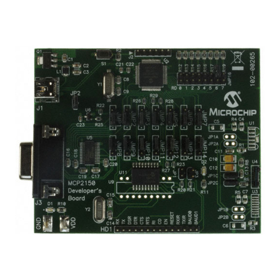
- Page 14 Product Overview The MCP2150 Developer’s Board, as shown in Figure 1-1, has the following hardware features: 1. Mini USB connector (for powering the board). 2. On Board +3.3V regulator for powering PIC18F65J50. 3. Hooks for an external regulated DC supply.
- Page 15 MCP2150 Developer’s Board User’s Guide FIGURE 1-1: MCP2150 DEVELOPER’S BOARD HARDWARE © 2009 Microchip Technology Inc. DS51869A-page 14...
- Page 16 Removing the jumper allows the MCP2150 portion to operate through the full voltage range of the MCP2150 (2.0V to 5.5V). When JP2 is connected, then the maximum voltage is restricted to the maximum voltage of the PIC18F65J50 device (3.6V).
- Page 17 MCP2150 Developer’s Board User’s Guide 1.3.2 Host UART Interface Connection Jumper Descriptions Figure 1-3 shows the five jumpers used to control the connection of the MCP2150’s Host UART signals. FIGURE 1-3: MCP2150 HOST UART INTERFACE CONNECTION MCP2150 Host Interface These fourteen jumpers connect the MCP2150’s Host UART...
-
Page 18: Pc Requirements
The PC used has three main requirements. These are: 1. Standard serial port. 2. USB port (to power the MCP2150 Developer’s Board). 3. Terminal emulation program. 4. IrDA standard driver installed, which treats the IR port as a virtual serial port. - Page 19 MCP2150 Developer’s Board User’s Guide NOTES: © 2009 Microchip Technology Inc. DS51869A-page 18...
-
Page 20: Chapter 2. Installation And Operation
(see Figure 2-1). To keep the board cost low, only a portion of the MCP2150 Developer’s Board is tested. This test covers the major portions of the system. The portions that are not tested are shown in Appendix C. -
Page 21: Configuring The Hyperterminal® Program
MCP2150 Developer’s Board User’s Guide THE DEMO SYSTEM The demo system setup requires a Primary Device and a MCP2150 Developer’s Board (Secondary Device). The Primary Device is a PC with an IR port (integrated IR port or IR Dongle). The Secondary Device is the embedded system, which is the MCP2150 Developer’s Board. - Page 22 (or IrDA to serial interface Dongle) data received on the DB-9 port. This demo shows the MCP2150 converting data between the IR port and the Host UART port. The Primary Device’s IR packet is decoded and any data is extracted and Transmitted on the Host UART interface.
- Page 23 MCP2150 Developer’s Board User’s Guide FIGURE 2-2: DEMO #1 CONFIGURATION - DIRECT TO UART (DB-9) MODE DB-9 Data Flow Transceivers Connector Note: This is the board configuration shipped to customers. © 2009 Microchip Technology Inc. DS51869A-page 22...
- Page 24 Installation and Operation FIGURE 2-3: DEMO #1 ALTERNATE POWER CONFIGURATION Jumper Shunt Removed DB-9 Data Flow Transceivers Connector © 2009 Microchip Technology Inc. DS51869A-page 23...
- Page 25 TABLE 2-2: DEMO #1 STEPS Step Action Result Place the Primary Device’s IR port and the MCP2150 — Developer’s Board on a flat surface about 25 cm (10 inches) apart, and with the IR ports facing each other. On the MCP2150 Developer’s Board: —...
- Page 26 Primary Device. This throughput will vary depending on the characteristics of the Primary Device. Figure 2-4 shows the system setup for this test, while Figure 2-5 shows the jumper configuration for the MCP2150 board. Lastly, Table 2-3 shows the steps for Demo #2 operation. Note:...
Need help?
Do you have a question about the MCP2150 and is the answer not in the manual?
Questions and answers