Table of Contents
Advertisement
CONTENTS
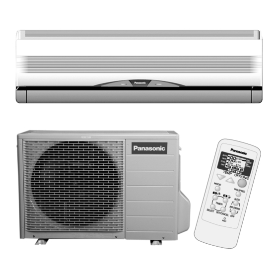
CS-PW18CKE CU-PW18CKE
Page
2
3
6
8
10
11
12
13
13
13
16
18
22
23
23
23
© 2004 Matsushita Industrial Corp. Sdn. Bhd.
(11969-T). All rights reserved. Unauthorized copying
and distribution is a violation of law.
Order No. MAC0401010C2
Air Conditioner
Page
23
24
32
32
35
38
41
41
42
46
48
52
52
Advertisement
Table of Contents


Need help?
Do you have a question about the CS-PW18CKE and is the answer not in the manual?
Questions and answers