Table of Contents
Advertisement
Quick Links
TABLE OF CONTENTS
1 Safety Precautions----------------------------------------------- 3
2 Specifications ----------------------------------------------------- 5
3 Features ------------------------------------------------------------- 7
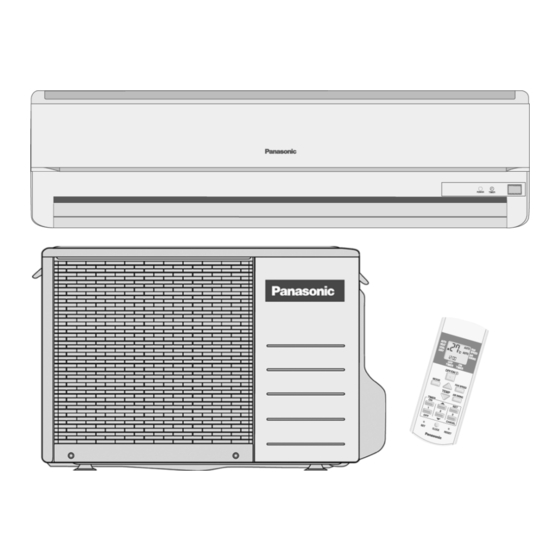
4 Location of Controls and Components ------------------- 8
4.1. Indoor Unit--------------------------------------------------- 8
4.2. Outdoor Unit ------------------------------------------------ 8
4.3. Remote Control -------------------------------------------- 8
5 Dimensions--------------------------------------------------------- 9
5.1. Indoor Unit & Remote Control -------------------------- 9
5.2. Outdoor Unit -----------------------------------------------10
6 Refrigeration Cycle Diagram --------------------------------11
7 Block Diagram----------------------------------------------------12
8 Wiring Connection Diagram ---------------------------------13
9 Electronic Circuit Diagram -----------------------------------14
9.1. Indoor Unit--------------------------------------------------14
9.2. Outdoor Unit -----------------------------------------------14
CS-PW18GKE CU-PW18GKE
PAGE
10 Printed Circuit Board ------------------------------------------ 15
10.1. Indoor Unit ------------------------------------------------- 15
10.2. Outdoor Unit----------------------------------------------- 17
10.3. Indicator & Receiver------------------------------------- 18
11 Installation Instruction ---------------------------------------- 19
11.1. Select The Best Location ------------------------------ 19
11.2. Indoor/Outdoor Unit Installation Diagram ---------- 19
11.3. Indoor Unit ------------------------------------------------- 20
11.4. Outdoor Unit----------------------------------------------- 23
12 Operation And Function -------------------------------------- 25
12.1. Heating Operation --------------------------------------- 25
12.2. Cooling Operation---------------------------------------- 26
12.3. Soft Dry Operation --------------------------------------- 27
12.4. Automatic Operation ------------------------------------ 28
12.5. Operation Control ---------------------------------------- 29
12.6. Indoor Fan Speed Control ----------------------------- 34
© 2007 Panasonic HA Air-Conditioning (M) Sdn. Bhd.
(11969-T). All rights reserved. Unauthorized copying
and distribution is a violation of law.
Order No. MAC0701003C2
Air Conditioner
PAGE
Advertisement
Table of Contents

Subscribe to Our Youtube Channel
Related Manuals for Panasonic CS-PW18GKE


Summary of Contents for Panasonic CS-PW18GKE
-
Page 1: Table Of Contents
9.1. Indoor Unit--------------------------------------------------14 12.5. Operation Control ---------------------------------------- 29 9.2. Outdoor Unit -----------------------------------------------14 12.6. Indoor Fan Speed Control ----------------------------- 34 © 2007 Panasonic HA Air-Conditioning (M) Sdn. Bhd. (11969-T). All rights reserved. Unauthorized copying and distribution is a violation of law. - Page 2 12.7. Outdoor Fan Speed Control --------------------------- 36 12.8. Vertical Airflow Direction Control --------------------- 36 12.9. Timer Control---------------------------------------------- 37 12.10. Random Auto Restart Control------------------------- 37 12.11. Remote Control Signal Receiving Sound ---------- 37 13 Servicing Mode -------------------------------------------------- 38 13.1. Auto OFF/ON Button ------------------------------------ 38 14 Troubleshooting Guide---------------------------------------- 39 14.1.
-
Page 3: Safety Precautions
1 Safety Precautions • Read the following “SAFETY PRECAUTIONS” carefully before perform any servicing. • Electrical work must be installed or serviced by a licensed electrician. Be sure to use the correct rating of the power plug and main circuit for the model installed. •... - Page 4 Carry out drainage piping as mentioned in installation instructions. If drainage is not perfect, water may enter the room and damage the furniture. Pb free solder has a higher melting point than standard solder; typically the melting point is 50 - 70°F (30 - 40°C) higher. Please use a high temperature soldering iron.
-
Page 5: Specifications
2 Specifications ITEM UNIT INDOOR UNIT OUTDOOR UNIT Performance Test Condition EUROVENT 5.10 Capacity BTU/h 17400 *kCal/h — W/W (Class) 2.91 BTU/hW 9.94 dB (A) High: 45, Low: 38 High: 55/- Noise Level Power level dB 5.30 Capacity BTU/h 18100 *kCal/h —... - Page 6 ITEM UNIT INDOOR UNIT OUTDOOR UNIT Fin Material Aluminium (Pre coat) Aluminium (Pre coat) Fin Type Slit Fin Corrugated Fin Heat Exchanger Row x Stage x FPI 2 x 15 x 21 2 x 20 x 17 Size (W x H x L) mm (inch) 810 x 315 x 25.4 684.6:719.2 x 508 x 44...
-
Page 7: Features
3 Features • High efficiency. • Serviceability Improvement • Compact design. - Removable and washable Front Panel. • Wider range of horizontal discharge air. • Air filter with function to reduce dust and smoke. • Environmental Protection • Automatic air swing and manual adjusted by Remote Control - Non-ozone depletion substances refrigerant (R410A) for vertical airflow. -
Page 8: Location Of Controls And Components
4 Location of Controls and Components 4.1. Indoor Unit 4.2. Outdoor Unit 4.3. Remote Control... -
Page 9: Dimensions
5 Dimensions 5.1. Indoor Unit & Remote Control... -
Page 10: Outdoor Unit
5.2. Outdoor Unit... -
Page 11: Refrigeration Cycle Diagram
6 Refrigeration Cycle Diagram... -
Page 12: Block Diagram
7 Block Diagram... -
Page 13: Wiring Connection Diagram
8 Wiring Connection Diagram... -
Page 14: Electronic Circuit Diagram
9 Electronic Circuit Diagram 9.1. Indoor Unit 9.2. Outdoor Unit... -
Page 15: Printed Circuit Board
10 Printed Circuit Board 10.1. Indoor Unit... -
Page 17: Outdoor Unit
10.2. Outdoor Unit... -
Page 18: Indicator & Receiver
10.3. Indicator & Receiver... -
Page 19: Installation Instruction
11 Installation Instruction 11.1. Select The Best Location INDOOR UNIT 11.2. Indoor/Outdoor Unit • There should not be any heat source or steam near the unit. Installation Diagram • There should not be any obstacles blocking the air circulation. • A place where air circulation in the room is good. •... -
Page 20: Indoor Unit
11.3. Indoor Unit 11.3.2. TO DRILL A HOLE IN THE WALL INSTALL SLEEVE 11.3.1. HOW TO FIX INSTALLATION PLATE PIPING The mounting wall is strong and solid enough to prevent it from 1. Insert the piping sleeve to the hole. the vibration. - Page 21 3. For the embedded piping (This can be used for left rear piping & left bottom piping also.)
- Page 22 11.3.4. CONNECT THE CABLE TO THE INDOOR UNIT 1. The inside and outside connecting cable can be connected without removing the front grille. 2. Connecting cable between indoor unit and outdoor unit shall be approved polychloroprene sheathed 5 x 1.5 mm flexible cord, type designation 245 IEC 57 or heavier cord.
-
Page 23: Outdoor Unit
11.4. Outdoor Unit 11.4.1. INSTALL THE OUTDOOR UNIT • After selecting the best location, start installation according to Indoor/Outdoor Unit Installation Diagram. 1. Fix the unit on concrete or rigid frame firmly and horizontally by bolt nut (ø10 mm). 2. When installing at roof, please consider strong wind and earthquake. -
Page 24: Evacuation Of The Equipment
11.4.3. EVACUATION OF THE EQUIPMENT WHEN INSTALLING AN AIR CONDITIONER, BE SURE TO EVACUATE THE AIR INSIDE THE INDOOR UNIT AND PIPES in the following procedure. 1. Connect a charging hose with a push pin to the Low side of a charging set and the service port of the 3-way valve. •... -
Page 25: Operation And Function
12 Operation And Function 12.1. Heating Operation • Heating operation can be set using remote control. • This operation is applied to warm the room temperature reaches the setting temperature set on the remote control. • The remote control setting temperature, which takes the reading of intake air temperature sensor, can be adjusted from 16°C to 30°C. -
Page 26: Cooling Operation
12.2. Cooling Operation • Cooling operation can be set using remote control. • This operation is applied to cool down the room temperature reaches the setting temperature set on the remote control. • The remote control setting temperature, which takes the reading of intake air temperature sensor, can be adjusted from 16°C to 30°C. -
Page 27: Soft Dry Operation
12.3. Soft Dry Operation • Soft Dry operation can be set using remote control. • Soft Dry operation is applied to dehumidify and to perform a gentle cooling to the room. • This operation starts when the intake air temperature sensor reaches the setting temperature on the remote control. •... -
Page 28: Automatic Operation
12.4. Automatic Operation • Automatic operation can be set using remote control. • This operation starts to operate with indoor fan at SLo speed for 25 seconds to judge the intake air temperature. • After judged the temperature, the operation mode is determined by referring to the below standard. •... -
Page 29: Operation Control
12.5. Operation Control (For 11.5.1 to 11.5.7 information applies only to Cooling and Soft Dry Operation) 12.5.1. Restart Control (Time Delay Safety Control) • When the thermo-off temperature (temperature which compressor stops to operate) is reached during:- - Cooling operation - the compressor stops for 3 minutes (minimum) before resume operation. - Soft Dry operation - the compressor stops for 6 minutes (minimum) before resume operation. -
Page 30: Compressor Reverse Rotation Protection Control
12.5.5. Compressor Reverse Rotation Protection Control • If the compressor is operating continuously for 5 minutes or longer and the temperature difference between intake air and indoor heat exchanger is 2.5°C (cooling mode) or less for continuous 2 minutes, compressor will stop and restart automatically. •... -
Page 31: Way Valve Control
(For 11.5.8 to 11.5.14 information applies only to Heating Operation) 12.5.8. Restart Control (Time Delay Safety Control) • When the thermo-off temperature (temperature which compressor stops to operate) is reached during:- - Heating operation - the compressor stops for 3 minutes (minimum) before resume operation. •... - Page 32 12.5.12. Hot Start Control • Hot Start Control is to prevent cool air discharge into the room when heating operation start. • When Heating operation starts, Indoor fan will not start until the indoor heat exchanger reaches 30°C as diagram shown. •...
- Page 33 a) Normal Deicing Time Diagram b) Overload Deicing Time Diagram...
-
Page 34: Indoor Fan Speed Control
12.6. Indoor Fan Speed Control • Indoor Fan Speed can be set using remote control. 12.6.1. Fan Speed Rotation Chart Speed CS-PW18GKE Cool, Dry Heat S Hi 1490 1470 1370 1270 1190 S Lo S Lo SS Lo Q SHi Q Hi —... - Page 35 • Auto Fan Speed during Soft Dry operation: 1. Indoor fan will rotate alternately between off and Lo-. 2. At the beginning of each compressor start operation, indoor fan will increase fan speed gradually for deodorizing purpose. 3. When compressor at turn off condition for 6 minutes, indoor fan will start fan speed at Lo- to circulate the air in the room. This is to obtain the actual reading of intake air temperature.
-
Page 36: Outdoor Fan Speed Control
12.7. Outdoor Fan Speed Control • There is only one speed for outdoor fan motor. • When the air conditioner is turned on, the compressor and the outdoor fan will operate simultaneously. • Likewise, both compressor and outdoor fan will stop at the same time if the unit is turned off. 12.8. -
Page 37: Timer Control
12.9. Timer Control • There are 2 types of timer, ON and OFF timer. • Both ON and OFF timer can be set by pressing ON or OFF button respectively. • By pressing ON/OFF operation button, ON Timer or OFF Timer will not be cancelled. •... -
Page 38: Servicing Mode
13 Servicing Mode 13.1. Auto OFF/ON Button • The “Auto OFF/ON Button” (behind the front grille) is used to operate the air conditioner if remote control is misplaced or mul- functioning. • Forced cooling operation is possible by pressing the “Auto OFF/ON Button” for more than 5s where “beep” sound is heard then release the button. -
Page 39: Troubleshooting Guide
14 Troubleshooting Guide 14.1. Refrigeration Cycle System In order to diagnose malfunctions, make sure that there are no electrical problems before inspecting the refrigeration cycle. Such problems include insufficient insulation, problem with the power source, malfunction of a compressor and a fan. The normal outlet air temperature and pressure of the refrigeration cycle depends on various conditions, the standard values for them are shown in the table on the right. -
Page 40: Relationship Between The Condition Of The Air Conditioner And Pressure And Electric Current
14.2. Relationship Between The Condition Of The Air Conditioner And Pressure And Electric Current Cooling Mode Heating Mode Condition of the air conditoner Low Pressure High Pressure Electric current Low Pressure High Pressure Electric current during operation during operation Insufficient refrigerant (gas leakage) Clogged capillary tube or Strainer... -
Page 41: Disassembly And Assembly Instructions
15 Disassembly and Assembly Instructions High voltages are generated in the electrical parts area by the capacitor. Ensure that the capacitor has discharged sufficiently before proceeding with repair work. Failure to heed this caution may result in electric shocks. 15.1. Indoor Electronic Controllers Removal Procedures 1. -
Page 42: Cross Flow Fan And Indoor Fan Motor Removal Procedures
15.2. Cross Flow Fan and Indoor Fan Motor Removal Procedures 1. In order to remove the Cross Flow Fan and Indoor Fan Motor, Control Board need to be taken out by releasing all the connectors as indicated below. a. Release the Earth Wire screw. (Fig. 5) b. -
Page 43: Remote Control Reset
7. Push up the Evaporator and pull out the Cross Flow Fan from shaft. By then, Fan Motor can be taken out. (Fig. 9) REMINDER - To reinstall the Fan Motor, put it back in place, adjust the position of the Fan Motor’s leadwire appropriately as shown in the Fig. -
Page 44: Technical Data
16 Technical Data 16.1. Thermostat Characteristics 16.1.1. CS-PW18GKE... -
Page 45: Sensible Capacity Chart
16.2. Sensible Capacity Chart CS-PW18GKE 230V Outdoor Temp. (°C) Indoor wet bulb temp. 17.0°C 5.06 3.83 1.60 4.73 3.68 1.72 4.40 3.53 1.84 4.00 3.36 1.99 19.0°C 5.10 1.75 19.5°C 5.55 4.02 1.63 5.19 3.86 1.676 4.83 3.71 1.88 4.39 3.53... -
Page 46: Operation Characteristics
16.3. Operation Characteristics 16.3.1. CS-PW18GKE CU-PW18GKE... -
Page 50: Exploded View And Replacement Parts List
17 Exploded View and Replacement Parts List 17.1. Indoor Unit Note: The above exploded view is for the purpose of parts disassembly and replacement. The non-numbered parts are not kept as standard service parts. - Page 51 REF NO. PART NAME & DESCRIPTION QTY. CS-PW18GKE CHASSY COMPLETE CWD50C1394 FAN MOTOR, DC 30W 3PH ARW51H8P30AC CROSS FLOW FAN COMPLETE CWH02C1010 SCREW - CROSS FLOW FAN CWH551146 BEARING ASS’Y CWH64K007 EVAPORATOR CWB30C2176 FLARE NUT (1/4) CWT251030 FLARE NUT (1/2) (5/8)
-
Page 52: Outdoor Unit
17.2. Outdoor Unit Note: The above exploded view is for the purpose of parts disassembly and replacement. The non-numbered parts are not kept as standard service parts. - Page 53 REF. NO. DESCRIPTION & NAME QTY. CU-PW18GKE CHASSY ASSY CWD50K2101 ANTI-VIBRATION BUSHING CWH50055 COMPRESSOR 5KS205DAE01 NUT-COMPRESSOR MOUNT CWH561049 SOUND PROOF MATERIAL CWG302253 FAN MOTOR BRACKET CWD541030 FAN MOTOR CWA951121J SCREW - FAN MOTOR BRACKET CWH551197 SCREW - FAN MOTOR MOUNT CWH55406J PROPELLER FAN ASSY CWH03K1006...
Need help?
Do you have a question about the CS-PW18GKE and is the answer not in the manual?
Questions and answers