Table of Contents
Advertisement
Quick Links
TH2883 Series Operation Manual
O p e r a t i o n M a n u a l
M M
M
O O
D D
E E
L L
O
D
E
L
I I
m m
p p
u u
l l
s s
I
m
p
u
l
T T
o o
n n
g g
h h
u u
i i
E E
l l
e e
c c
T
o
n
g
h
u
i
E
l
e
c
: :
:
A A
d d
d d
r r
e e
s s
s s
N N
A
d
d
r
e
s
s
N
D D
i i
s s
t t
r r
i i
c c
t t
, ,
C C
h h
a a
n n
D
i
s
t
r
i
c
t
,
C
h
a
n
( (
) )
: :
(
)
:
T T
E E
L L
0 0
5 5
1 1
9 9
T
E
L
0
5
1
9
( (
) )
: :
(
:
F F
A A
X X
0 0
5 5
1 1
9 9
F
A
X
0
5
1
9
: :
:
E E
M M
A A
I I
L L
s s
a a
l l
e e
E
M
A
I
L
s
a
l
e
H H
t t
t t
p p
: :
/ /
/ /
w w
w w
w w
. .
t t
o o
H
t
t
p
:
/
/
w
w
w
.
t
o
T T
H H
2 2
8 8
8 8
3 3
T
H
2
8
8
3
e e
W W
i i
n n
d d
i i
s
e
W
i
n
d
i
t t
r r
o o
n n
i i
c c
s s
C C
o o
. .
, ,
t
r
o
n
i
c
s
C
o
.
,
O O
. .
3 3
, ,
T T
i i
a a
n n
S S
O
.
3
,
T
i
a
n
S
g g
z z
h h
o o
u u
, ,
J J
i i
a a
n n
g g
s s
u u
g
z
h
o
u
,
J
i
a
n
g
s
, ,
,
8 8
5 5
1 1
3 3
2 2
2 2
2 2
2 2
8
5
1
3
2
2
2
2
)
8 8
5 5
1 1
0 0
9 9
9 9
7 7
2 2
8
5
1
0
9
9
7
2
s s
@ @
t t
o o
n n
g g
h h
u u
i i
. .
c c
o o
s
@
t
o
n
g
h
u
i
.
c
o
n n
g g
h h
u u
i i
. .
c c
o o
m m
. .
c c
n n
n
g
h
u
i
.
c
o
m
.
c
n
1
S S
8 8
- -
5 5
/ /
S S
4 4
- -
S
8
-
5
/
S
4
-
n n
g g
T T
e e
s s
t t
e e
n
g
T
e
s
t
e
L L
t t
d d
. .
L
t
d
.
h h
a a
n n
R R
o o
a a
d d
, ,
X X
h
a
n
R
o
a
d
,
, ,
C C
h h
i i
n n
a a
u
,
C
h
i
n
a
8 8
5 5
1 1
1 1
3 3
3 3
4 4
2 2
8
5
1
1
3
3
4
2
m m
. .
c c
n n
m
.
c
n
5 5
5
r r
r
i i
n n
B B
e e
i i
X
i
n
B
e
i
Advertisement
Table of Contents

Related Manuals for Tonghui TH2883S4-5


Summary of Contents for Tonghui TH2883S4-5
- Page 1 TH2883 Series Operation Manual O p e r a t i o n M a n u a l : : : ( ( ) ) , , : : ( ) , : ( ( ) ) : : (...
-
Page 2: Table Of Contents
5.1 Introduction to icons of soft keys ..................5-1 5.2 Measurement setup page ....................5-1 5.2.1 Step ........................5-2 5.2.2 Mode ........................5-2 5.2.3 CH1-CH8(TH2883S8-5), CH1-CH4(TH2883S4-5) Channel setup ...... 5-3 5.2.4 Samp- can be set in TEST mode ................5-3... - Page 3 TH2883 Series Operation Manual 5.2.5 Test Imp- can be set in TEST mode ............... 5-3 5.2.6 Erase Imp- can be set in TEST mode ..............5-3 5.2.7 Volt ADJ- can be set in TEST mode............... 5-4 5.2.8 Start Volt- can be set in BDV test mode ..............5-4 5.2.9 End Volt- can be set in BDV test mode ..............
- Page 4 TH2883 Series Operation Manual 6.3.4 LAN interface ...................... 6-11 6.4 About ..........................6-13 Chapter 7 User guide ........................7-1 7.1 Use of keys ........................7-1 7.1.1 Use of the roller ..................... 7-1 7.1.2 Switch the display page ..................7-1 7.1.3 Numeric arrow key ....................7-1 7.2 Basic measurement ......................
- Page 5 TH2883 Series Operation Manual 9.1 Basic information ......................9-2 9.2 Electrical characteristics ....................9-3 9.2.1 DC isolated output ....................9-3 9.2.2 Isolated input ......................9-4 9.3 Jumper setup on HANDLER interface ................9-5 Chapter 10 Package contents and warranty .................. 10-1 10.1 Package contents ......................
-
Page 6: Chapter 1 Overview
TH2883 Series Operation Manual Chapter 1 Overview Thank you for your use of our products. Before the use of it, please locate the items listed in this manual to ensure nothing is missing. If in the case that any item is missing, please contact us immediately. -
Page 7: Production Introduction
TH2883 Series Operation Manual poor ventilation. In addition, the instrument will generate high voltage, so it must be used at room temperature and in the absence of much dust. 1.1 Production introduction Due to the influence of wire material, magnetic material, framework and manufacture technics, winding products such as transformers, motor windings may have defects of low insulation between winding layers, circles and leads. -
Page 8: Operation Environment
TH2883 Series Operation Manual Figure 1-2 Typical self-attenuation oscillation wave 1.2 Operation environment 1.2.1 Power supply Voltage: 198V-242V AC, 99V-121V AC Power frequency: 47.5Hz-63Hz Consumption: ≤200VA 1.2.2 Environment temperature and humidity Normal working temperature: 0℃~40℃, Humidity: ≤ 90%RH Referential working temperature: 20℃± 8℃, Humidity: ≤ 80%RH Transferring environment temperature: 0℃~50℃m, Humidity: ≤... -
Page 9: Chapter 2 General Specifications
TH2883 Series Operation Manual Chapter 2 General specifications Chapter 2 General specifications 2.1 Specifications Specifications TH2883-1 TH2883-5 TH2883-10 TH2883S8-5 TH2883S4-5 Impulse voltage 30V-1200V 100V~5000 500V-10kV 100V-5000V 100V-5000V 5V steps 20V steps 10V steps 10V steps ± 5%± 5V 10V steps ±... -
Page 10: Comparison Methods
TH2883 Series Operation Manual Chapter 2 General specifications USB disk : external memory Interface Handler,RS232C,USB Device,USB Host,Lan Power Power supply 110V/220V ± 10% 50Hz/60Hz ± 5% ≤200VA Power consumption General specifications Working Temperature 0℃ - 40℃ ≤75% R.H. environment Humidity Safty electromagnetic IEC61010-1:2001,IEC61326-2-1:2005... -
Page 11: Corona Discharge Comparison
TH2883 Series Operation Manual Chapter 2 General specifications is the ratio of the differential portion area size to the area size of the standard waveform between A and B, expressed as a percentage. Figure 2-2 Differential Area Comparison The differential area size reflects the value of inductance and total energy loss. This method is especially effective to detect the differences of inductance L between the standard winding and the tested winding. -
Page 12: Differential Phase Comparison
TH2883 Series Operation Manual Chapter 2 General specifications Then, a new effective value can be set by adding 20% to the maximum corona discharge value. In order to ensure the correctness of the new value, user can test these coils once more and observe the corona PASS or FAIL. -
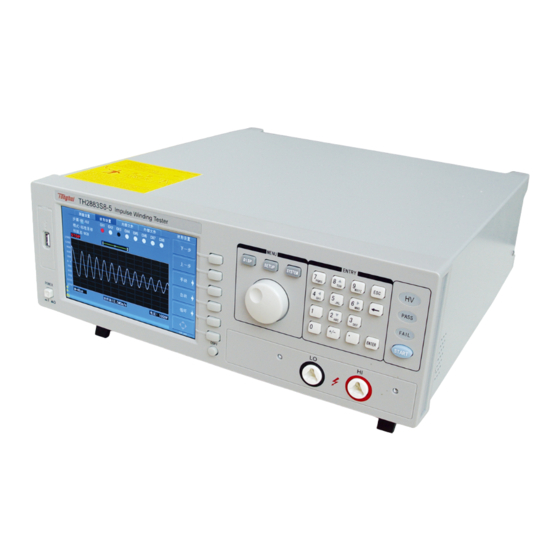
Page 13: Chapter 3 Panels And Display
TH2883 Series Operation Manual Chapter 3 Panels and display Chapter 3 Panels and display 3.1 Front panel TH2883S8-5 Impulse Winding Tester MENU ENTRY DISP SETUP SYSTEM PQRS WXYZ PASS FAIL ENTER START POWER COPY Serial Number Name Instruction Brand and model 320×... - Page 14 High voltage terminal Output high voltage. Although all 8 channels (TH2883S4-5 is equipped with 4 channels) are not equipped with it, this high voltage terminal has high voltage output when pressing START. Ground terminal Low terminal for high voltage test, connecting to a test fixture and DUT with 15.
-
Page 15: Rear Panel
Connect the power. Scanning Test Terminal TH2883S8-5 has 8 scanning test terminals, from CH1 to CH8 TH2883S4-5 has 4 scanning test terminals, from CH1 to CH4 Test terminal High voltage output terminal, the function is the same as that of the high voltage terminal 15 on the... -
Page 16: Introduction To Display Area
TH2883 Series Operation Manual Chapter 3 Panels and display front panel. Test terminal It is the GND terminal connected to the DUT with 11 and 16 on the front panel. Table 3-2 Rear Panel Instruction 3.3 Introduction to display area Specific definition for each area: Voltage Show the voltage of waveform... - Page 17 TH2883 Series Operation Manual Chapter 3 Panels and display Display format: XX/XX. The first two digits display the step number of the current waveform display and comparison and the latter two digits display the total numbers of steps. The maximum steps can be set is 20. Measurement result Show the final measurement result.
-
Page 18: Chapter 4 Introduction To [Disp]
TH2883 Series Operation Manual Chapter 4 Introduction to [DISP] Chapter 4 Introduction to [DISP] Press the DISP menu key to enter the < MEAS DISP> page (the default page). In this page, measurements are taken and the test waveform is displayed. Some function settings such as standard sampling (Standard), comparison setting (Compare), measurement function (Measure), auxiliary function (Utility), statistic function (Statistics), display color of the waveform, test step, sampling rate, etc. -
Page 19: Display
TH2883 Series Operation Manual Chapter 4 Introduction to [DISP] Compare Enter the Compare setup submenu. Under this menu, states of the four compare methods, compare parameters can be set. Measure Enter the Compare function submenu. Under this menu, wave voltage, wave time, wave frequency can be set. -
Page 20: Measure
TH2883 Series Operation Manual Chapter 4 Introduction to [DISP] means this method is turned on, while means off. State Position Lighten this icon to enable the roller. The start point, the end point 0000-6000 or both the start and the end points will be selected by the press of the roller. -
Page 21: Utility
TH2883 Series Operation Manual Chapter 4 Introduction to [DISP] selected by the press of the roller. Then revolve the roller to change the position of the high and the low limits. The differential value between the high and the low limits (Δs) is as shown on the second soft key. -
Page 22: Modify
TH2883 Series Operation Manual Chapter 4 Introduction to [DISP] Clear Clear the current statistic results. Save Save the current statistic data to external U disk. The default format is csv. Return to the main menu. 4.3.6 Modify See 4.3.1.4. -
Page 23: Chapter 5 Introduction To [Setup]
TH2883 Series Operation Manual Chapter 5 Introduction to [SETUP] Chapter 5 Introduction to [SETUP] Press SETUP to enter the <Meas Setup> page. This is a toggle key, by pressing it, the displayed page can be toggled among <Meas. Setup>, <Match Setup>, <Int. File> and <Ext. File>. 5.1 Introduction to icons of soft keys ... -
Page 24: Step
Chapter 5 Introduction to [SETUP] Figure 5-1 Measure setup page Follow parameters can be set in <Setup>. Step (Step) Mode (Mode) CH1-CH8(TH2883S8-5), CH1-CH4(TH2883S4-5) Channel Setup Impulse voltage (Imp Volt) Sampling rate (Samp) Test impulse (Test Imp) ... -
Page 25: Samp- Can Be Set In Test Mode
Channel setup TH2883S8-5 provides 8 channels from CH1 to CH8, TH2883S4-5 provides 4 channels from CH1 to CH4. Move the cursor to the corresponding channel, CLOSE, HIGH and LOW can be set for this channel. Red means the current mode of the channel is HIGH. Black means the current mode of the channel is LOW. -
Page 26: Volt Adj- Can Be Set In Test Mode
TH2883 Series Operation Manual Chapter 5 Introduction to [SETUP] They are fine adjustment soft keys used to change the number of impulses by 1. Lighten this key to enable the numerical arrow key. Respectively press 8, 2, 4, 6, the cursor will move up, down, left and right. -
Page 27: Comparator
TH2883 Series Operation Manual Chapter 5 Introduction to [SETUP] Step volt = Start Volt * Volt Step. Move the cursor to this zone, following soft keys will be displayed. They are coarse soft keys used to change Volt Step by a resolution of 10%. ... -
Page 28: Diff(Limit) (Area Size, Diff Zone, Phase Diff
In Match Setup interface, the sample handling for standard waveform of each test step can be set and checked. The setup of 8 channels (4 channels for TH2883S4-5) for the current selected step are displayed at the right corner of the interface. Red means the current mode of the channel is HIGH. -
Page 29: Step
TH2883 Series Operation Manual Chapter 5 Introduction to [SETUP] Figure 5-2 Match setup page 5.3.1 Step Select the step set in Meas. Setup interface and make sample handling of standard waveform of each step. The instrument provides three kinds of sample mode: Manual, Auto and Loop. ... -
Page 30: Mode
TH2883 Series Operation Manual Chapter 5 Introduction to [SETUP] Turn up to load the sample waveform at higher frequency. Select Select the sample waveform at current frquency as standard waveform. Select & Check Make a sample test at the current frequency. If the comparison result is within the error range, select the sample waveform at current frquency as standard waveform and return to the Mainmenu;... -
Page 31: Std.name-Available In Sample Mode
TH2883 Series Operation Manual Chapter 5 Introduction to [SETUP] is selected, Step No. is available. Lighten this key to enable the numerical arrow key. Respectively press 8, 2, 4, 6, the cursor will move up, down, left and right. 5.3.3 Std.Name-available in Sample mode Std.Name is displayed when the mode is Sample, it is invalid in other mode. - Page 32 TH2883 Series Operation Manual Chapter 5 Introduction to [SETUP] Figure 5-3 Internal File Int. File consists of file number (NO), file name (File), Date/ Time, Load. Following soft keys can be used in this page. Load Press this key to load a file stored in the internal non-volatile memory. As figure 5-3 indicates, using the arrow key or the roller can select the needed file.
-
Page 33: Ext. File
TH2883 Series Operation Manual Chapter 5 Introduction to [SETUP] saved as the default name-<Unnamed>. Pressing ESC can exit the operation of saving file. Letters from A to Z, numbers from 0 to 9, and underline, etc. can be used for a file name. ... - Page 34 TH2883 Series Operation Manual Chapter 5 Introduction to [SETUP] without inputting the folder name, the folder will be named as the default name-<FOLDERxx> (xx is a number ranging from 01 to 99.). Pressing ESC can exit the operation of creating. Letters from A to Z, numbers from 0 to 9, and underline, etc.
-
Page 35: Chapter 6 Introduction To [System]
TH2883 Series Operation Manual Chapter 6 Introduction to [SYSTEM] Chapter 6 Introduction to [SYSTEM] Press SYSTEM to enter System. This is a toggle key, the press of which will make the displayed page toggled among System, Parameter, Interface, About. 6.1 System Figure 6-1 shows the System page. -
Page 36: Brightness
TH2883 Series Operation Manual Chapter 6 Introduction to [SYSTEM] 6.1.1 Brightness Move the cursor to this zone, following soft keys will be displayed. They are soft keys used to increase and decrease the LCD display. Lighten this key to enable the numerical arrow key. Respectively press 8, 2, 4, 6, the cursor will move up, down, left and right. -
Page 37: Password
TH2883 Series Operation Manual Chapter 6 Introduction to [SYSTEM] Full Full screen will be copied. Wave Only wave zone will be copied. Lighten this key to enable the numerical arrow key. Respectively press 8, 2, 4, 6, the cursor will move up, down, left and right. -
Page 38: Time
TH2883 Series Operation Manual Chapter 6 Introduction to [SYSTEM] They are soft keys used to adjust date by 1 day. Lighten this key to enable the numerical arrow key. Respectively press 8, 2, 4, 6, the cursor will move up, down, left and right. -
Page 39: Wave Disp
TH2883 Series Operation Manual Chapter 6 Introduction to [SYSTEM] 6.2.1 Wave Disp If user only wants the comparison result, the wave display can be switched off so as to obtain a test speed much faster. Move the cursor to this zone, following soft keys will be displayed. ... -
Page 40: Delay Time
TH2883 Series Operation Manual Chapter 6 Introduction to [SYSTEM] TRIGGER commands are sent to TH2883 via RS232SC, USBTMC, USBCDC or LAN interface. Lighten this key to enable the numerical arrow key. Respectively press 8, 2, 4, 6, the cursor will move up, down, left and right 6.2.3 Delay Time Delay time refers to the time between the end of a measurement and the start of the next measurement. -
Page 41: I/O
TH2883 Series Operation Manual Chapter 6 Introduction to [SYSTEM] 6.3.1 I/O Move the cursor to the I/O: zone, following soft keys will be displayed. RS232C Set RS232 interface as the I/O interface. Set USB interface as the I/O interface. ... - Page 42 TH2883 Series Operation Manual Chapter 6 Introduction to [SYSTEM] 9 pin connector used in IMB AT compatible computer. User can purchase the serial interface cable from our company. TH2883’s baud rate, data bit, stop bit, parity bit and Tx term can be set.
-
Page 43: Usb Interface
TH2883 Series Operation Manual Chapter 6 Introduction to [SYSTEM] Lighten this key to enable the numerical arrow key. Respectively press 8, 2, 4, 6, the cursor will move up, down, left and right. 6.3.3 USB interface Move the cursor to this zone, following soft keys can be used. ... - Page 44 TH2883 Series Operation Manual Chapter 6 Introduction to [SYSTEM] Figure 6-7 USBCDC has not been installed. 6.2.3.2 USBTMC interface USB (Universal Serial Bus) remote control system controls the instrument through the USB interface. This connection conforms to USBTMC-USB488 and USB2.0 protocols. Connect USB interfaces on PC and TH2883 through a USB cable.
-
Page 45: Lan Interface
Chapter 6 Introduction to [SYSTEM] Figure 6-8 PC has installed USBTIMC drive When user is using USBTMC interface, labview software can be used to access the instrument. Tonghui provides Labview software for controlling TH2883. See Labview instruction manual for more details. 6.3.4 LAN interface LAN (Local Area Network) can access TH2883 by two ways. - Page 46 TH2883 Series Operation Manual Chapter 6 Introduction to [SYSTEM] Figure 6-9 Network parameters of Host computer Figure 6-10 Network parameters of TH2883 6.2.4.1 Access TH2883 through a browser When TH2883 is accessed through a browser, it acts as a WEB server. User can access TH2883 6-12...
-
Page 47: About
TH2883 Series Operation Manual Chapter 6 Introduction to [SYSTEM] by Internet Explorer (IE6.0 or upgraded version). Steps of the access to TH2883 trough a browser (assume that the instrument IP is 192.168.1.140) (1) Start up Internet Explorer. (2) Input http://192.168.1.140/ in the address zone and then press ENTER to finish inputting. - Page 48 TH2883 Series Operation Manual Chapter 6 Introduction to [SYSTEM] Figure 6-12 About Following soft keys can be used in the About page. Reset Press this key to reset the instrument. Factory Press this key to reset the instrument to factory settings. 6-14...
-
Page 49: Chapter 7 User Guide
TH2883 Series Operation Manual Chapter 7 User guide Chapter 7 User guide 7.1 Use of keys 7.1.1 Use of the roller The roller can be used as a roller and a key. The roller can be rotated in clockwise and anti-clockwise directions, thus achieving parameter setups. -
Page 50: Basic Measurement
TH2883 Series Operation Manual Chapter 7 User guide 7.2 Basic measurement Start up the instrument to enter the default measurement display page. The primary display zone shows the tested waveform. When Single Display is selected in Disp Setup, the secondary one shows parameters of corona or test. 7.2.1 Non-standard test This test is applicable to trial sample test. -
Page 51: Technology Application
TH2883 Series Operation Manual Chapter 7 User guide 7.4 Technology application 7.4.1 Test objects Turn-to-turn and layer-to-layer short Turn-to-turn short refers to the short caused by the insulation damage between turns. Layer-to-layer short occurs in the coil consisting of multiple layers. There are two kinds of short: direct short and pull arc short, both of which are shown as more dissipation. -
Page 52: Settings Of Comparison Method
TH2883 Series Operation Manual Chapter 7 User guide Both Area size comparison and corona comparison can be used to test coils of motor, solenoid and relay. Area size comparison, according to energy dissipation, can effectively detect layer-to-layer short and circle-to-circle short, while corona comparison is mainly applied to detect coil’s internal insulation failure. - Page 53 TH2883 Series Operation Manual Chapter 7 User guide value of the corona but also the chart record of differential area after each test. The chart can help user observe the changing regularity of the area differences during the test from the start voltage to the end voltage.
-
Page 54: Chapter 8 Command Reference
TH2883 Series Operation Manual Chapter 8 SCPI Command reference Chapter 8 Command reference 8.1 Command structure TH2883 series has two types of commands: GPIB common commands and SCPI commands. The GPIB common commands are defined in IEEE std.488.2-1987, and these commands are common for all devices. - Page 55 TH2883 Series Operation Manual Chapter 8 SCPI Command reference case.) For example: COMPARATOR:AREASIZE ON = COMP:AREA ON The command header should be followed by a question mark (?) to generate a query for that command. For example: COMP:AREA? Multiple command rules: The semicolon (;) can be used as a separator to execute multiple commands on a single line.
-
Page 56: Notation Conventions And Definitions
TH2883 Series Operation Manual Chapter 8 SCPI Command reference including units. For example: disp:page meas = DISP:PAGE MEAS = DiSp:PAGe MEas 8.2 Notation conventions and definitions The following characters are used in the command syntax. : A colon is used to separate the higher level commands and the lower level commands. ;... - Page 57 TH2883 Series Operation Manual Chapter 8 SCPI Command reference Figure 8-2 DISPlay subsystem command tree The :PAGE command sets the display page. The :PAGE? query returns the abbreviated page name displayed on the LCD screen. Command syntax: DISPlay:PAGE <page name> <page name>...
- Page 58 TH2883 Series Operation Manual Chapter 8 SCPI Command reference < MEAS DISP > indicates that the current displayed page is the measurement display page. < MEAS SETUP > indicates that the current displayed page is the measurement setup page. <SYSTEM SETUP> indicates that the current displayed page is the system setup page. <...
-
Page 59: Ivoltage Subsystem Commands
TH2883 Series Operation Manual Chapter 8 SCPI Command reference Where, the grid display mode is ON. the grid display mode is OFF. For example: WrtCmd( “DISP:GRID ON” ); the grid display mode is ON. Query syntax: DISPlay:GRID? Return format: <NL^END> Where, Off means that the current grid display mode is OFF. - Page 60 TH2883 Series Operation Manual Chapter 8 SCPI Command reference Figure 8-3 IVOLTage subsystem command tree The [:VOLTage] command sets the impulse voltage for testing. The [:VOLTage]? query returns the current impulse voltage value. Command syntax: IVOLTage [:VOLTage] <value> Where, <value> can be NR1, NR2 or NR3 format followed by KV or V and the value must be between100V to 5000V.
- Page 61 TH2883 Series Operation Manual Chapter 8 SCPI Command reference Query syntax: IVOLTage:TIMPulse? Return format: <NR1><NL^END> The :EIMPulse command the times of erasing impulses for testing. The :EIMPulse? query returns the current times of erasing impulses. Command syntax: IVOLTage: EIMPulse <number> Where, <number>...
-
Page 62: Srate Subsystem Commands
TH2883 Series Operation Manual Chapter 8 SCPI Command reference 8.3.3 SRATE subsystem commands The Sample RATE subsystem commands set the sample rate and the time base zoom. Figure 8-4 shows the Sample RATE subsystem command tree. Figure 8-4 Sample RATE subsystem command tree The :RATE command sets the sample rate. -
Page 63: Comparator Subsystem Commands
TH2883 Series Operation Manual Chapter 8 SCPI Command reference 8.3.4 COMParator subsystem commands The COMParator subsystem commands set the compare conditions, such as Areasize, Diffzone, Corona and Phasediff. Figure 8-5 shows the command tree of the COMParator subsystem commands. Figure 8-5 COMParator subsystem command tree The BDV here stands for the destruction test, and its comparison setting method is the same as the non-destructive test, and will be merged when writing the command syntax and query syntax of the destructive test and the non-destructive test. - Page 64 TH2883 Series Operation Manual Chapter 8 SCPI Command reference Command syntax: COMParator[:STATe] Where, 1 (decimal49) is equal to ON; the comparator is ON. 0 (decimal48) is equal to OFF; the comparator is OFF. For example: WrtCmd( “COMP ON” ); turn on the comparator function. Query syntax: COMParator[:STATe]? Return format: <COMP STAT><NL^END>...
- Page 65 TH2883 Series Operation Manual Chapter 8 SCPI Command reference The :AREAsize:RANGe command sets the comparison range of Areasize comparator. The :AREAsize:RANGe? query returns the current comparison range of Areasize comparator. Command syntax: COMParator:AREAsize:RANGe <start pot>, <end pot> Where, <start pot> start point of comparison range. NR1 format, range from 0 to 6000, without unit. <end pot>...
- Page 66 TH2883 Series Operation Manual Chapter 8 SCPI Command reference Return format: <NL^END> The :DIFFzone:RANGe command sets the comparison range of the Diffzone comparator. The :DIFFzone:RANGe? query returns the current comparison range of the Diffzone comparator. Command syntax: COMParator:DIFFzone:RANGe <start pot>, <end pot> Where, <start pot>...
- Page 67 TH2883 Series Operation Manual Chapter 8 SCPI Command reference Where, 1 (decimal 49) When the function is ON 0 (decimal 48) When the function is OFF For example: WrtCmd( “COMP:CORO ON” ); turn on the Corona comparator. Query syntax: COMParator:COROna[:STATe]? Return format: <NL^END>...
- Page 68 TH2883 Series Operation Manual Chapter 8 SCPI Command reference COMParator:PHASediff[:STATe] Where, 1 (decimal 49) When the function is ON 0 (decimal 48) When the function is OFF For example: WrtCmd( “COMP:PHAS ON” ); turn on the Phasediff comparator. Query syntax: COMParator:PHASediff[:STATe]? Return format: <NL^END>...
-
Page 69: Trigger Subsystem Commands
TH2883 Series Operation Manual Chapter 8 SCPI Command reference 8.3.5 TRIGger subsystem commands The TRIGger subsystem command group is used to trigger a measurement or to set the trigger mode. Figure 8-6 shows the TRIGger subsystem command tree. Figure 8-6 TRIGger subsystem command tree The [:IMMediate] command triggers a measurement. -
Page 70: Statistic Subsystem Commands
TH2883 Series Operation Manual Chapter 8 SCPI Command reference <NL^END> 8.3.6 STATistic subsystem commands The STATistic subsystem commands set the statistic function to ON or OFF, clear or save statistic data. Figure 8-9 shows the STATistic subsystem command tree. Figure 8-7 STATistic subsystem command tree The [:STATe] command sets the statistic function to ON or OFF. -
Page 71: Wadjust Subsystem Commands
TH2883 Series Operation Manual Chapter 8 SCPI Command reference 8.3.7 WADJust subsystem commands The WADJust subsystem command is mainly used to display the time base transformation of the output waveform and the left and right movement of the waveform. Figure 8-8 shows the WADJust subsystem command tree. - Page 72 TH2883 Series Operation Manual Chapter 8 SCPI Command reference Figure 8-9 Standard WAVE subsystem command tree The :SMODE command sets the sample mode of the standard waveform. The :SMODE? query returns the current sample mode. Command syntax: SCYCLe SWAVE:SMODE OCYCLe OSAMPle Where, SCYCLe...
-
Page 73: Fetch? Subsystem Commands
TH2883 Series Operation Manual Chapter 8 SCPI Command reference The :CHOose command is used to select the required standard waveform. Command syntax: SWAVE:CHOose For example: WrtCmd( “SWAVE:CHO” ); NOTE: 1. This command is available only on <MEAS DISP> page. 2. - Page 74 TH2883 Series Operation Manual Chapter 8 SCPI Command reference If the waveform data is not ready, the FETCh SWAVE? and FETCh TWAVE? query will be executed after the current measurement or next measurement is finished. The :CCRESULT? query output the total judgment result of the device under test. Query syntax: FETCh:CCRESULT? Return format: <NR1>...
-
Page 75: Measure Subsystem Commands
TH2883 Series Operation Manual Chapter 8 SCPI Command reference NOTE: TH2883 returns the comparison result when the comparator is turned on. TH2883 returns 9.9E37 when the AREA SIZE, DIFF ZONE or PHASE DIFF comparator is turned off. TH2883 returns 9999 when the CORONA comparator is turned off. The :VOLTage? query returns the current voltage value in the set voltage range. - Page 76 TH2883 Series Operation Manual Chapter 8 SCPI Command reference Figure 8-11 MEASure subsystem command tree The :VOLTage command sets the measurement range of voltage. The :VOLTage? query returns the current voltage range. Command syntax: MEASure:VOLTage <upper>,<lower> Where, <upper> is the upper limit of voltage, NR1 format, ranging from 1 to 248 without unit. <lower>...
-
Page 77: Abort Subsystem Command
TH2883 Series Operation Manual Chapter 8 SCPI Command reference The :TIME command sets the time range. The :TIME? query returns the current time range. Command syntax: MEASure:TIME<start, end> Where, <start> is the start point of time, NR1 format and ranging from 1 to 598 without unit. <end>... -
Page 78: Measstep Subsystem Commands
TH2883 Series Operation Manual Chapter 8 SCPI Command reference the saved page. The :SAVE:STATe or STORe:STATe command is used to save the current setting data to a file. Command syntax: MMEMory:STORe:STATe <record number, “filename”> Where, <record number> is the file serial number ranging from 1 to 100 , NR1 format without unit. <“filename”>... - Page 79 TH2883 Series Operation Manual Chapter 8 SCPI Command reference test step. Command syntax: MeasSTEP: STEP<setup> <setup> is as follows: ADD adds a test step reduces one test step returns to the previous test step DOWN returns to the next test step For example: WrtCmd ("MeasSTEP:STEPADD");...
-
Page 80: Wavestep Subsystem Commands
TH2883 Series Operation Manual Chapter 8 SCPI Command reference 8.3.14 WaveSTEP subsystem commands WaveSTEP subsystem commands are used for waveform settings such as standard waveforms, standard wave copying, and comparison tests. Figure 8-14 shows the WaveSTEP subsystem command tree. Figure 8-14 WaveSTEP subsystem command tree The :UP command is used for the setting of the waveform step. -
Page 81: Common Commands
TH2883 Series Operation Manual Chapter 8 SCPI Command reference Query syntax: WaveSTEP: WaveMODE ? The query returns: <mode><NL^END> <mode> is as follows: NONE This step does not have any settings SAMPLE This step is the standard wave sampling mode. SW.COPY This step is the standard wave copy mode. -
Page 82: Error And Warning Message
TH2883 Series Operation Manual Chapter 8 SCPI Command reference commands for standard waveform test. *IDN? The *IDN? query returns the TH2883’s ID information. Query syntax: *IDN? Return format: <product>,<version>,<NL^END> Where, <product> TH2883-5 Impulse Winding Tester <version> software version number 8.4 Error and warning message The bus commands may have some spelling errors, syntax errors or wrong parameters. - Page 83 TH2883 Series Operation Manual Chapter 8 SCPI Command reference value is 100. Trigger ignores! When TH2883 is in the testing state, all trigger signals will be ignored. Command ignores! Some command may be ignored. For example: DISP:PAGE MSET When TH2883 is in the testing state, this command will be ignored. Error syntax! Grammatical errors For example: WrtCmd ("MMEM:STOR:STAT 105,"#TH2883*")
-
Page 84: Chapter 9 Handler Interface
TH2883 Series Operation Manual Chapter 9 Handler interface Chapter 9 Handler interface 9.1 Basic information The handler interface employs a 9-pin DB connector. Pin sequence is as follow. (side view) The signal definitions for each pin are described as follows: Note: The / (back slash) in the signal name means that the signal is asserted when low level PIN ... -
Page 85: Electrical Characteristics
TH2883 Series Operation Manual Chapter 9 Handler interface when use. The timing diagram for handler interface is displayed in above figure, T1 is the trigger pulse width and the minimum pulse width is 1 us. T2 is the delay time, after the foregoing measurement completed to next trigger signal;... -
Page 86: Isolated Input
TH2883 Series Operation Manual Chapter 9 Handler interface Figure 9-1 Simplified diagram of the output signals A simplified diagram of the output signals is shown in Figure 9-1. * is the default jumper setting when shipped from factory. That is to say, the default jumper setting is to use external voltage source. -
Page 87: Jumper Setup On Handler Interface
TH2883 Series Operation Manual Chapter 9 Handler interface Figure 9-2 Simplified diagram of the input signal In figure 9-2, the default jumper setting is to use external voltage source. Actually, the input signals and the output signals use the external voltage source together. The Current-limit resistor is used to limit the current and the default resistor is only suitable for external voltage source range from 5V to 8V. - Page 88 TH2883 Series Operation Manual Chapter 9 Handler interface Figure 9-3 Jumper position on the Handler interface board As above figure shown, when shipped from the factory, both jumpers are set at the upper position. If you want to apply the internal power supply, you must set both jumpers at the lower position. Likewise, when using external power supply to substitute the internal power supply, the two jumpers should be set at the same time.
-
Page 89: Chapter 10 Package Contents And Warranty
This warranty does not apply in the event of misuse or abuse of the product or as a result of unauthorized alterations or repairs. Tonghui will, without charge, repair or replace, at its option, defective product or component parts.
Need help?
Do you have a question about the TH2883S4-5 and is the answer not in the manual?
Questions and answers