
Subscribe to Our Youtube Channel
Related Manuals for Tonghui TH9310 Series


Summary of Contents for Tonghui TH9310 Series
- Page 1 TH9310/20 Series AC/DC Withstanding Voltage/ Insulation Resistance Tester Operation Manual Tonghui Electronic Co.,Ltd. www.tonghui.com.cn ◇1...
- Page 2 Manual Printing History The manual printing data and part number indicate its current edition. The printing date changes when a new edition is printed. The manual part number changes when extensive technical changes are incorporated. TH9310/20 Series Operation Manual Ver1.6.………………..……………….2018.7 ◇2...
-
Page 3: Table Of Contents
Content Chapter 1 Setup ..............................6 1.1 Precautions for Use ............................. 6 1.2 Precautions for Moving..........................7 1.3 Connecting the AC Power Cord ......................... 7 1.4 Grounding ..............................7 1.5 Checking Operations ........................... 7 1.6 Other Specifications ............................ 8 Chapter 2 Precautions on Handling ........................9 2.1 Prohibited Operations .......................... - Page 4 Chapter 4 Basic operation ..........................22 4.1 Interface structure overview ........................22 4.2 Instruction of panel function interface and parameter ................23 4.2.1 SETUP ............................... 24 4.2.2 TEST (Take AC for example) ......................25 4.2.3 SYSTEM ............................25 4.2.4 FILE ..............................27 4.3 Test item interface and parameter setup ....................
- Page 5 5.5 MMEM Subsystem Commands ........................ 57 5.6 FETCH Subsystem Commands ........................ 57 5.7 Other Commands ............................58 5.8 Command debugging sequence ........................ 58 ◇5...
-
Page 6: Chapter 1 Setup
Chapter 1 Setup This chapter describes the procedures from unpacking to installation to operation checking. 1.1 Precautions for Use Be sure to observe the following precautions when using the tester. Do not use the tester in a flammable atmosphere. To prevent explosion or fire, do not use the tester near alcohol, thinner, or other combustible materials, or in an atmosphere containing such vapors. -
Page 7: Precautions For Moving
1.2 Precautions for Moving When moving the tester to the installation site or otherwise transporting it, take the following precautions: Before moving the tester, turn off the power switch. Transporting the tester with its POWER switch on can lead to electric shock and damage. When moving the tester, Disconnect all wires from it. -
Page 8: Other Specifications
same as that indicated on the rear panel of the tester. When the power is turned on, the tester lights all LEDs on the front panel and self-diagnosis is started. Before starting up the tester, confirm that all LEDs are on to ensure safety. It is particularly dangerous to start a test when the DANGER lamp is broken. -
Page 9: Chapter 2 Precautions On Handling
Chapter 2 Precautions on Handling This chapter describes the precautions to be followed in the handling of this tester. When using the tester, take utmost care to ensure safety. ! WARNING :The tester derivers a 5 kV test voltage which can cause human injury or death. When operating the tester, be extremely careful and observe the cautions, warnings, and other instructions given in this chapter. -
Page 10: Precautions On Testing
You may do either (a) or (b) first. But be sure to do both. 1. Turn OFF the power switch of the tester. 2. Disconnect the AC power cord of the tester from the AC line receptacle. 2.3 Precautions on Testing Wearing Insulation Gloves ... -
Page 11: Dangerous States Of Failed Tester
probe, and DUT are charged to a high voltage. The tester is equipped with a discharge circuit, but some time is nonetheless required to discharge them after the output is cut off. There is a danger of electric shock during discharge. To avoid electric shock, take the utmost care to ensure that the DUT, test lead wire, probe, and highly charged parts around the output terminal are not touched. -
Page 12: To Ensure Long-Term Use Without Failures
2.6 To Ensure Long-Term Use without Failures The withstanding voltage-generating block of the tester is designed to release half the rated amount of heat, in consideration of the size, weight, cost, and other factors of the tester. The tester must therefore be used within the ranges specified below. -
Page 13: Front Panel
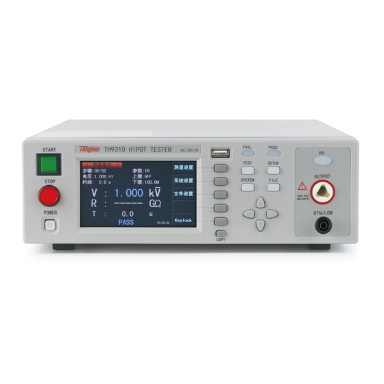
Chapter 3 Part names and Functions This chapter describes the names and functions of components such as switches, displays, and connectors on the front and rear panels. 3.1 Front Panel Figure 3-1 gives a brief description of the front panel for TH9310/20 series. FAIL PASS START... -
Page 14: Function
3.1.6 FUNCTION Select mode, system and interface. ● TEST Press the key and the corresponding key lights, the instrument is ready to test. ● SETUP Press the key and the corresponding key lights, the instrument enters parameter setting; ● SYSTEM Press the key and the corresponding key lights, the system setting interface will be displayed;... -
Page 15: Fan
HV OUTPUT RTN/LOW HIGH VOLTAGE MAX:5kV AC WARNING: FOR CONTINUED PROTECTION AGAINST FIRE HAZARD, REPLACE ONLY WITH THE SAME TYPE AND RATING OF FUSE AS SPECIFIED FOR THE LINE VOLTAGE BEING UTILIZED. 110V/220V~50/60Hz CAUTION: NO OPERATOR SERVICEABLE PARTS INSIDE REFER SERVICING TO QUALITIFIED PERSONNEL. HANDLE RS-232C SIGNAL... -
Page 16: Rs232C Serial Interface
3.2.7 RS232C serial interface Serial communication, realize the communication with the computer. 3.2.8 USB serial communication interface Realize the communication with the computer. Through this interface, the computer can control the instrument by using the control instruction set. 3.2.9 HANDLER interface Compared to PLC interface, the HANDLER interface has no INTERLOCK function in interface signal. -
Page 17: Description
With this multi-channel module, rapid connection can be achieved through test fixture without changing ports during the testing process. The test connection diagram is as follows: 3.4 Description TH9320: Provide 5kV AC/20mA withstanding voltage, 6kV DC/10mA withstanding voltage and insulation resistance test. TH9310: Provide 5kV AC/10mA withstanding voltage, 6kV DC/5mA withstanding voltage and insulation resistance test. - Page 18 (DC). The distortion of the waveform is less than 3%. In TH9310 series high voltage module, there is a AB power amplifier circuit and a 50VA high voltage transformer, which can realize the output of 5kV/10mA and the output of 6kV/5mA (DC).
- Page 19 Figure 3-3 AC voltage load regulation ■ DC withstanding voltage test 5kV/10mA(TH9320/A)5kV/5mA(TH9310/A) TH9310/20 series can provide DC withstanding voltage test of wide voltage range (Max. output DC is 6kV). The automatic voltage regulation and voltage load regulation of 600Hz frequency hardware is less than 1%+10V.
- Page 20 ■ Open and short detection: judge the reliability of the DUT before starting the high voltage to ensure the accuracy and safety of high voltage test. Open and short detection can judge the distribution impedance current of more than 100PF. When the current is less than this value, the current acquisition circuit resolution of the instrument can not distinguish the connection of open circuit and the test component accurately.
- Page 21 danger of electric shock..TH9310/20 has the enforced rapid discharge function after DC withstanding voltage test and insulation resistance test finish. ■ Reinforced safety In order to improve the safety, TH9310/20 series allocate many devices and safe functions including safe output terminal, discharge function and ground wire current detection. The ground wire current detection means in high voltage test circuit, when return current flowing through shell is larger than 0.45mA, the high voltage output will be cut off, thus there will be no shock current in high voltage to protect the operator’s safety.
-
Page 22: Chapter 4 Basic Operation
Chapter 4 Basic operation 4.1 Interface structure overview This chapter describes the operation of withstanding voltage and insulation resistance. The following figure is the interface structure: TEST Start test File change SETUP STEP:01/01 & check AC FUNC SYSTEM1 SYSTEM SETUP1 SYSTEM SETUP2 FILE SAVE... -
Page 23: Instruction Of Panel Function Interface And Parameter
4.2 Instruction of panel function interface and parameter This section is mainly describe the function interface and relevant parameter in accordance with the order of sofeware process and interface relevance. Initial state introduction of the instrument 1. After starting up, the system enters into the last used setup interface before shutdown last time. -
Page 24: Setup
5. The system will start upgrading automatically. It will reboot automatically after finishing upgrading. 6. Enter into the lock system keyboard(F5) and input the system lock password. The default password is 9310. 7. Log-in the system interface and enter into the system password item. 8. -
Page 25: Test (Take Ac For Example)
4.2.2 TEST (Take AC for example) MEAS SETUP MEAS SETUP STEP: 01/01 FUNC VOLT: 0.050 UPPR: 1.000 SYSTEM TIME: LOWR: SETUP FILE V: 0 . 0 0 0 SETUP I: 0 . 0 0 0 0 . 0 Message Figure 4.2.2 AC test interface Note:... - Page 26 SYSTEM 1 Interface SystemSetup 1 PgDn PASS HOLD: PASS BEEP STEP HOLD: CONT FAIL BEEP LONG GFI: KEY BEEP STEP HOLD: STRT DLY: TURN MODE: OFFSET: DISP MODE: DATA SHORT HIGH TEST SAFT ARC MODE Value FILE NORMAL CTRL MODE: STEP MODE Message OFF~KEY~99.9S...
-
Page 27: File
Turn on the key beep. Set the test delay time from srarting test to 0.1~99.9S the beginning of the test of step 1. STRT DLY By default, the instrument starts testing after being ready. OFF~ON Set the clear of base number. OFFSET Obtaining the base number under the current test condition. - Page 28 <INTERNAL FILE> Internal File 11 :11 FILE-N1.STA 2011/ 11/11 External File 13 :14 FILE-N2.STA 2012/ 05/ 20 Exit 19 :09 FILE-N3.STA 2013/09/19 09 :09 FILE-N4.STA 2099/ 09/ 09 PAGE 1 4.2.4.1 FILE interface Instruction: Serial Shortcut Description Definition number option Memory selection Internal Internal file interface.
-
Page 29: Test Item Interface And Parameter Setup
(TH9320 series) 0.001~10.00mA Current upper limit value withstanding voltage (TH9310 series) 0.001~20.00mA Low limit current value of AC, it must be LOWR smaller than the upper limit value (TH9320 series) 0.001~10.00mA Low limit current value of AC, it must be... -
Page 30: Dc Withstanding Voltage Test Parameter Setup
No requirement for the arc 0.1~999.9S Test time of AC withstanding voltage TIME No requirement for the test time 0.1~999.9S Voltage rise time of AC high voltage test RISE The minimum voltage rise time is 0.1s. FALL 0.1~999.9S Voltage fall time of AC high voltage test The minimum voltage fall time is 0.1s. -
Page 31: Open And Short Detection (Os) Parameter Setup
4.3.3 Insulation resistance (IR) test parameter setup: (Figure 4.4.3): MEAS SETUP STEP: 01/01 FUNC: VOLT: 0.050 UPPR: TIME: LOWR: 0.1M RISE: RANG: AUTO FALL: ENTER Message Figure 4.3.3 IR setup interface Instruction: VOLT: 0.050~1.000kV Voltage value of IR test 0.1M~50.00G High limit value of IR UPPER:... -
Page 32: Mf (Multi-Channel Follow)
Figure 4.3.4 OS setup interface Instruction: OPEN 10% ~ 100% Percentage of open judge value and standard value STEP:1% SHORT OFF~100% ~ 500% Percentage of short judge value and standard value STEP: 10% STAN Previous standard Sampling standard value (see NOTE) value Acquisition of the distribution parameter as standard Note:... -
Page 33: Ck (Multi-Channel Contact Check)
MEAS SETUP SCAN: | 3 | 4 | 5 | 6 | 7 | 8 STEP: 01/01 FUNC WAVE: Message Figure 4.3.5 MF setup interface Instruction: SCAN | 3 | 4 | 5 | 6 | 7 | 8 Controllable 8 output channels Connected with high voltage terminal GREEN Connected with test terminal... -
Page 34: Test Function Theory And Instruction
4.4 Test function theory and instruction This section describes the test theory and instruction of ground connection, ground wire current detection and arc detection according to the order of the test procedure. Block flow diagram of the instrument Start test Test delay Test voltage rise Electric wall... -
Page 35: Start Up Test
4.4.1 Start up test In measurement mode, after the tester check the test conditions and the connection with DUT, press START to start up test. 4.4.2 Test delay After the delay set by STA DELY in SYSTEM, the tester will start measurement. 4.4.3 Test voltage rise Some DUTs are voltage-sensitive, so this function is useful. -
Page 36: Current Over Limit And Arc Detection (Arc) Function
quite serious and may cause coma or death of the operator. Where permitted by the product, it is recommended to turn on the ground wire current detection. 4.4.8 Current over limit and arc detection (ARC) function Current over limit is divided as: current low limit, current high limit, current over limit and arc detection. -
Page 37: Fail Judgment
instrument, the pulse width is greater than 1mS. Zone C: Arc detection circuit. This circuit only samples the mutational amplitude occurred in the current, signal high pass filters out low frequency → voltage peak contrast → pulse lock. When the current mutation rise is near the set value, the pulse width is about 1uS-1mS. -
Page 38: Scan Multi-Channel Structure And Use
2. Select OFFSET item in SYSTEM interface and set it as ON. 3. Press GET, the instrument will start high voltage test and treat the current test value as the zero position value. 4. Press “STOP” button to stop the test if the customer has not set the test time. NOTE: when in GET, do not connect the product with the test terminal. -
Page 39: Structure And Use Of Handler And Signal Interface Circuit
NOTE: 1. In the multi-channel state, the output port of the hipot tester has the original function and it can be used as a common terminal. 2. Multi-channel output port connection is set by the user. Pay special attention when using: Do not connect extra high voltage wiring to avoid danger. -
Page 40: Control Interface Instruction
4. SIGNAL interface additionally provides the power supply with +24V output voltage and 0.5A output current. Coordinating with HANDLER interface control signal, it can be used for driving indicator light, optoelectronic switch and miniwatt electromagnetic valve. (See picture below) 4.6.2 Control interface instruction Control interface is generally used as remote control and test synchronization or indication. -
Page 41: Other Interface And Function
3. Internal power supply performance: The unregulated output is about 24V, please confirm before use. The maximum transient output current of the internal power shall not be larger than 0.5A and the current of long working hours shall be less than 0.2A. Self- contained power is necessary if larger current is needed. -
Page 42: Chapter 5 Serial Port Commands Instruction
Chapter 5 Serial port commands instruction Brief description for command format: 1. The instrument commands only describe the actual characters accepted or sent by the instrument. 2. Command characters are ASCII characters. 3. The command data "<???>" are all ASCII character strings. The system default format is an integer or floating-point number. -
Page 43: Function Subsystem Commands
Query syntax: DISPlay:PAGE? Return format: MEAS 5.3 FUNCtion Subsystem Commands NOTE: the operating interface must be in Setup interface(DISPlay:PAGE MSETup) 5.3.1 FUNCtion subsystem commands--mainly used to set the test parameters of test function Command Tree: : : : Command Value command comman command... -
Page 44: Commands For Ac Setup Function
FUNC:SOURce:STEP NEW Create an empty test programme to write a brand new test programme FUNC:SOURce:STEP INS Add a new test item in existing test programme (STEP). FUNC:SOURce:STEP DEL Delete the current test item in existing test programme (STEP). FUNC:SOURce:STEP <sn> Edit the <sn>... - Page 45 Command message: FUNC:SOUR:STEP 1:AC:UPPC 1 Query message: FUNC:SOUR:STEP 1:AC:UPPC? Return message: 1.000 FUNC:SOURce:STEP:AC:LOWC To set /inquiry about the LOWER current for ACW test --Syntax: Command message: FUNC:SOUR:STEP <sn>:AC:LOWC<current> Query message: FUNC:SOUR:STEP <sn>:AC:LOWC? --Data<current>: Data format: float Data range: 0~20.000 mA (0 is OFF) TH9320 0~10.000 mA (0 is OFF) TH9320...
- Page 46 --Data<time>: Data format: float Data range: 0~999.9 (0 is OFF) Data accuracy: 0.1 Data unit: s --Example: Set the RISE time for ACW test in STEP1 as 1s. Command message: FUNC:SOUR:STEP 1:AC:RTIM 1 Query message: FUNC:SOUR:STEP 1:AC:RTIM? Return message : 1.000 FUNC:SOURce:STEP:AC:FTIM To set /inquiry about the FALL time for ACW test --Syntax:...
-
Page 47: Commands For Dc Setup Function
Query message: FUNC:SOUR:STEP <sn>:AC:FREQ? --Data<frequency>: Data format: character Data range: 50/60 Data accuracy: Data unit: Hz --Example: Set the test frequency for ACW test in STEP1 as 50Hz. Command message: FUNC:SOUR:STEP 1:AC:FREQ:50 Query message: FUNC:SOUR:STEP 1:AC:FREQ? Return message: 50 FUNC:SOURce:STEP:AC:CH1 To set /inquiry about the milti-channel value --Syntax: Command message:... - Page 48 FUNC:SOURce:STEP:DC:UPPC To set /inquiry about the UPPER current for DCW test --Data<current>: Data format: float Data range: 0.001 ~10.000 mA TH9320 0.001 ~5.000 mA TH9310 Data accuracy: 0.001mA Data unit: mA FUNC:SOURce:STEP:DC:LOWC To set /inquiry about the LOWER current for DCW test --Data<current>: Data format: float Data range: 0~10.0 mA (0 is OFF)
-
Page 49: Commands For Ir Setup Function
Data unit: mA FUNC:SOURce:STEP:DC:WTIM To set /inquiry about the wait time for DCW test --Syntax: Command message: FUNC:SOUR:STEP <sn>:DC:WTIM<time> Query message: FUNC:SOUR:STEP <sn>:DC:WTIM? --Data<sn>: --Data<time>: Data format: float Data range: 0~999.9(0 is OFF) Data accuracy: 0.1 Data unit: s --Example: Set the wait time for DCW test in STEP1 as 1s. - Page 50 Data unit: V FUNC:SOURce:STEP:IR:UPPC To set /inquiry about the UPPER resistance for IR test --Data< resistance>: Data format: float Data range: 0~1E4 (0 is OFF) MΩ Data accuracy: 1.0 MΩ Data unit: MΩ FUNC:SOURce:STEP:IR:LOWC To set /inquiry about the LOWER resistance for IR test --Data<resistance>: Data format: float Data range: 0.1~1E4 MΩ...
-
Page 51: Commands For Os Setup Function
FUNC:SOURce:STEP:IR:CH1 To set /inquiry about the milti-channel value --Data<channel value>: Data format: character Data range: HIHG/LOW/OPEN 5.3.6 Commands for OS Setup Function NOTE: for the basic format, please refer tocommands for AC Setup function. FUNC:SOURce:STEP:OS:OPEN To set /inquiry about the OPEN rate for OS test --Syntax: Command message: FUNC:SOUR:STEP <sn>:OS:OPEN<rate>... -
Page 52: System Subsystem Commands
100.0 is returned. FUNC:SOURce:STEP:OS:GET Outputs the capacitance Command message: FUNC:SOUR:STEP <sn>:OS: GET The instrument will automatically sample the standard capacitance value after impedance transformation of the current. 5.4 SYSTem Subsystem Commands NOTE: it is valid only in system setup interface, use command(DISPlay:PAGE SYSTem)to switch. Command Tree: →... - Page 53 SYSTem:PASS To set /inquiry about the time for PASSHOLD --Syntax: Command message: SYST:PASS <time> Query message: SYST:PASS? --Data< rate>: Data format: float Data range: 0.3~99.9 Data accuracy: 0.1 Data unit: s --Example: Set the PASSHOLD as 1.0s. Command message: SYST:PASS 1 --Return message Query message: SYST:PASS?
- Page 54 Query message: SYST:GFI? --Data< ON/OFF>: Data format: character Data range: 0(OFF), 1(ON) --Example: Set the GR CONT as ON, Command message: SYST:GFI ON or SYST:GFI:1 --Return message Query message: FUNC: :SYST:GFI? If the state for GR CONT is 1, 1 is returned. SYSTem:DISP To set /inquiry about the state for DISP --Syntax:...
- Page 55 0 is returned. SYSTem:TURN To set /inquiry about the state for TURN --Syntax: Command message: SYST:TURN<ON/OFF> or <1/0> Query message: SYST:TURN? --Data< ON/OFF>: Data format: character Data range: 0(OFF), 1(ON) --Example: Set the TURN as ON, Command message: SYST:TURN ON or :SYST: GFI: 1 --Return message Query message: SYST: TURN? If the state for GR TURN is 1,...
- Page 56 SYST:OFFS? --Data< ON/OFF/GET>: Data format: character Data range: 0(OFF), 1(ON), GET(get the reset value) --Example: Set the OFFS as ON, Command message: SYST:OFFS ON or :SYST: OFFS 1 --Return message Query message: SYST: OFFS? If the state for OFFS is 1, 1 is returned.
- Page 57 Data range: 0 (NORMAL), 1 (REPEAT) --Example: Set the working mode as REPEAT, Command message: SYST: SMOD 1 --Return message Query message: SYST: SMOD? If the working mode is REPEAT, 1 is returned. 5.5 MMEM Subsystem Commands NOTE: it is valid only in file interface, use command(DISPlay:PAGE MMEM)to switch. MMEM:STOR Save the current file to file number --Syntax:...
- Page 58 *IDN Inquiry about the model and version information of the instrument Return message: <manufacturer>,<model>,<firmware><NL^END> Where, <manufacturer> Gets the manufacturer name (Tonghui) <model> Gets the machine model (such as TH9320/9310) <firmware> Gets the version number of firmware (such as Version1.0.0) For example: WrtCmd(“*IDN?”);...
- Page 59 4. Edit the interface switching instruction (DISP: PAGE <NAME>), and see if the instrument interface switching is normal. 5. DISP:PAGE_SYST (NL^END) To enter the system interface. (SYST commands) 6. SYST:FAIL _1 (NL^END) To set system parameters. 7. DISP:PAGE_MSET (NL^END) To enter the setup interface. (FUNC commands) 8.
Need help?
Do you have a question about the TH9310 Series and is the answer not in the manual?
Questions and answers