
Related Manuals for Tonghui TH9010 Series


Summary of Contents for Tonghui TH9010 Series
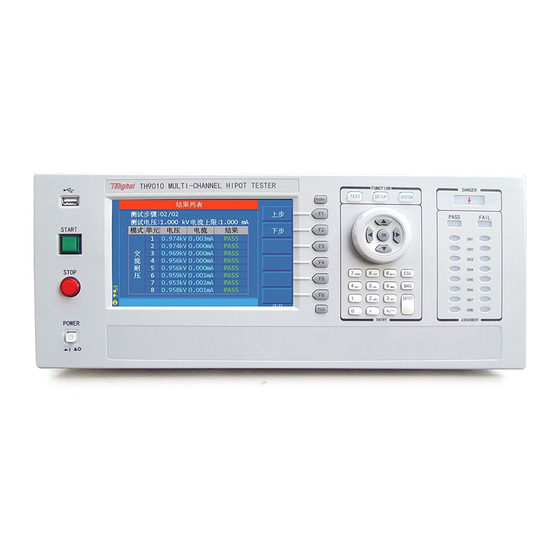
- Page 1 TH9010 Series Multi-channel Hipot Tester Operation Manual Tonghui Electronic Co.,Ltd. www.tonghui.com.cn ◇1...
-
Page 2: Table Of Contents
Content Chapter 1 Unpacking and Installing ......................5 1.1 Precautions for Use..............................5 1.2 Precautions when moving ............................5 1.3 Connecting AC Power Cables ..........................6 1.4 Grounding ................................6 1.5 Operation Check ..............................6 1.6 Other Characteristics ............................7 Chapter 2 Precautions on Handling ......................8 Prohibited Operation Behavior ........................8 Actions When in Emergency ........................8 Precautions in Testing ...........................9... - Page 3 3.2.9 USB serial communication interface ............................ 15 3.2.10 HANDLER interface ............................... 15 3.2.11 SINGLE interface ................................15 3.3 Multi-unit scanner description ........................... 15 3.3.1 EXTENSION: serial number of the current controller ......................16 3.3.2 UNIT n: Unit n ................................. 16 3.3.3 CH n: scan channel n .................................
- Page 4 Chapter 5 Serial Port Commands Instruction ..................45 5.1 DISPlay Subsystem Commands ........................45 5.2 MMEM Subsystem Commands......................... 45 5.3 FUNCtion Subsystem Commands ........................46 5.3.1 FUNCtion test, Stop instruction ............................46 5.3.2 FUNCtion File Editing Function Commands ........................46 5.3.3 FUNCtion Test Function, Test Parameter Commands ......................
-
Page 5: Chapter 1 Unpacking And Installing
Chapter 1 Unpacking and Installing This chapter tells some of the check points that must be performed after you receive the instrument and things you must know before installing the instrument. 1.1 Precautions for Use Be sure to follow the rules below when using the instrument: ... -
Page 6: Connecting Ac Power Cables
Moving the instrument without disconnecting the cable may result in damage to the cable or drop the instrument during handling it. 1.3 Connecting AC Power Cables The power cord is supplied by Tonghui along with the instrument. Do not use an AC power cord that is not included with the instrument. Connection order: 1. -
Page 7: Other Characteristics
Tonghui Share The Future Technology TH9010 Parallel Multi-Unit Hipot Tester VERSION :1.0.9 Copyright(c)2017 http//www.tonghui.com.cn Changzhou Tonghui Electronic Co . , Ltd 1.6 Other Characteristics (1)Power consumption: power consumption < 1000VA (2) Dimensions (W*H*D): 430mm*175mm*630mm; (3) Weight: about 35kg. Input Voltage... -
Page 8: Chapter 2 Precautions On Handling
Chapter 2 Precautions on Handling This chapter describes the precautions to be followed in the handling of this tester. When using the tester, take utmost care to ensure safety. ! WARNING: The tester derives a 5 KV test high voltage, care must be taken when operating the instrument and follow the cautions, warnings, and other instructions given in this chapter. -
Page 9: Precautions In Testing
2.3 Precautions in Testing ■ Wearing Insulation Gloves When handling the tester, be sure to wear insulation gloves in order to protect yourself against high voltages, even though, it is forbidden to touch the live conductor by hand when high voltage test is conducting. -
Page 10: Handling For Dangerous State Of Faulty Tester
DANGER light is off and remove the hidden danger. As soon as the output is cut off, the tester’s discharge circuit starts forced discharging. Do not disconnect the DUT during a test or prior to the completion of discharging. Under normal circumstances, it can be guaranteed that the test circuit voltage will be within the safe voltage range at the end of discharge. -
Page 11: Conditions For Ensuring Long-Time Trouble-Free Working
2.6 Conditions for ensuring long-time trouble-free working Due to the dimension, weight, and actual use of the instrument, the voltage generation module of the instrument has a small heat dissipation design. Therefore, the instrument is recommended for use in the following ranges. If the fan has been in continuous operation for 30 minutes, the instrument must be suspended;... -
Page 12: Chapter 3 Panel Description
Chapter 3 Panel Description This chapter describes the basic operating characteristics of the TH9010 Series instruments. Before using the TH9010 Series instruments, please read this chapter in detail so that you can quickly learn the operation of the TH9010 Series. -
Page 13: File Function Key
achieving quick operation. 3.1.7 File Function Key It is used to save existing settings to the internal storage area of the instrument. 3.1.8 Numeric keypad It is used to enter data for test parameters and modify the current set parameters. 3.1.9 Indicator Area ●... -
Page 14: Copy
● SYSTEM Press this button to light and display the system setting interface (SYSTEM); it is used to configure parameters not related to test but related to the test system, such as display, communication, etc. 3.1.14 Copy COPY the picture of the current screen to the USB memory, which must be pre-plugged into the front panel jack. -
Page 15: High Voltage Output Terminal (One Per Test Unit)
3.2.4 High voltage output terminal (one per test unit) High voltage output terminal of high voltage test interface. 3.2.5 Power socket: self-contained fuse box For input AC power, please use the voltage within the specified input voltage range of the instrument. Please use the power cord that comes with the instrument. -
Page 16: Extension: Serial Number Of The Current Controller
3.3.1 EXTENSION: serial number of the current controller Each host can expand 4 controllers, in the order of connection 1-4, the corresponding indicator will light when the instrument sends data. Host Scan Chanel Controller Serial Number 1-4 Scan Chanel #1 Controller 1-4 Scan Chanel 5-8 Scan Chanel #2 Controller... -
Page 17: Signal In/Out: Control Signal Input (Female) / Output (Male)
3.3.4 SIGNAL IN/OUT: Control signal input (female) / output (male) Control uses series control and the input terminal is connected to the host or the output signal that is switched through the controller. The output terminal is used to connect to the signal input terminal of the next controller, to achieve control signal switch. - Page 18 Test power Each high voltage module of the TH9010 series is a PWM power amplifier circuit and a 50VA high voltage transformer, to achieve AC: 5kV/10mA, DC: 6kV/5mA output, the distortion of the waveform is less than 3%. If the customer need to continuous current output, in order to ensure the reliability of the instrument, maximum output time is 60 seconds when working above 60% of rated output current.
- Page 19 Figure 3-3 AC voltage load regulation DC withstand voltage test 6kV/5mA TH9010 Series provides DC withstand voltage test over a wide voltage range (maximum output DC 6kV). Automatic voltage adjustment of 600Hz frequency hardware, voltage load regulation rate ≤1%+10V.
- Page 20 DUT remains fully charged, therefore there is a danger of electric shock. The TH9010 series has a forced fast discharge function on the DUT after the DC withstand voltage test and insulation resistance test are completed.
- Page 21 Easy operability TH9010 series is easy to operate, ensuring that users do not have difficulty to use. The instrument lists all test parameters in the setting interface. Use the arrow keys to select a parameter from the LCD display interface, then use the function button to modify the parameters, customers can start to test after setting the data.
-
Page 22: Chapter 4 Basic Operation
Chapter 4 Basic operation 4.1 Interface structure overview The following figure is the interface structure: TEST Start Test File modification STEP:01/01 SETUP and inspection AC parameters SYSTEM Test (channel Envi control) FILE Int.File SAVE Ext.File LOAD Figure 4-1 Operation Steps Interface Instructions: ... -
Page 23: Panel Function Interface And Parameter Description
the "TEST" interface. 4.2 Panel function interface and parameter description This section introduces the functional interface and related parameters of the instrument based on the software flow and interface correlation, to guide users to understand the function and use of the instrument. -
Page 24: Test Interface
4.2.1 Test Interface The test interface is used to start the test process to test the DUT according to the existing requirements. Use the "TEST" button to enter The interface is as follows: (taking AC as an example) Figure 4.2.1 AC Test Interface Note: 1. -
Page 25: System Interface
Note: After modifying the data in the SETUP interface, switch the interface to TEST and the instrument will save all data modifications. Please be careful not to shut down directly after modifying the data to avoid data loss. The interface is as follows: Figure 4.2.2 AC SETUP Interface Test file modification instructions STEP:... - Page 26 result processing, test process control, and instrument communication scheme. Press the “SYSTEM” button to enter, press the “SYSTEM” button again to switch to the sub-interface. Note: After modifying the data in the SETUP interface and SYSTEM interface, you must switch the interface to save all data modifications.
- Page 27 2. Test environment related sub-interface Figure 4.2.3.2 Test environment related interface Interface parameter notes: Password setting (PASS WORD): Set the key lock password, the instrument default password: 666666. The F4 function key of the password setting state is the system firmware upgrade button, the firmware program must be inserted into the U disk of the instrument.
- Page 28 4. HANDLER communication interface setting Level type description: 1. High Level: Active high at output and the output interface optocoupler is open. (Test board indicator is off) 2. Low Level: Active low at output, output interface optocoupler is turned on. (Test board indicator is on) 3.
-
Page 29: File Storage Interface
Setting Description Mark PASS At the end of the test, the signal is valid when all unit tests pass. FAIL At the end of the test, the signal is valid when all unit tests fail. Undefined(Backup) WAIT When the test is started, when there is no output at high voltage, the signal is valid. -
Page 30: Test Project Interface And Parameter Description
The external file operation interface is indicated: Figure 4.2.4.2 External file operation interface Interface Description: I: internal file. Storage area divided inside the instrument, save or call the test file E: External U disk storage file. U disk to store, save or call test files, enable to use the current settings file on other instruments conveniently. -
Page 31: Dc Withstanding Voltage Test Parameter Setting
TH9320 series AC lower limit current value, must be less than the LOWR: 0.001~20.00mA UPPER value TH9010 series AC lower limit current value, must be less than the 0.001~10.00mA UPPER value Lower limit is not required AC arc current maximum allowable ARC:... -
Page 32: Ir Insulation Resistance Test Parameter Setting
Figure 4.3.2 DC setting interface DC withstand voltage (DC) test parameters are described below High voltage test voltage value VOLT: 0.050~6.000kV Current upper limit UPPER: 0.1uA~10.00mA Current upper limit 0.1uA~5.00mA Current lower limit, should be less than the UPPER limit LOWR:... -
Page 33: Os Circuit Test Parameter Setting
2uA, 20uA, 200uA, 2mA, 10mA Fixed range mode: can use I=U/R to estimate the range to speed up testing TH9010 series 1uA, 10uA, 100uA, 1mA, 5mA Fixed range mode: can use I=U/R to estimate the range to speed up testing Note: 1. - Page 34 Figure 4.3.4 OS setting interface Open short circuit detection (OS) test parameters are as follows OPEN: 10%~100%, 1% Open circuit determination threshold lower limit SHRT: OFF~100%~500% Short circuit determination threshold upper STEP: 10% limit STAN: Previous Standard Standard Value (check remark) Get the current distribution parameter as the standard value Remarks:...
-
Page 35: S.ck Single-Ended Contact Check Parameter Setting
standard value 60P. Connect multiple damaged DUTs to record GET data range: STAN >100P to confirm short value Parameter setting calculation: Assume that STAN is set to 60P. Open value: Lower Limit=20P/60P=33%, OPEN Upper Limit=50P/60P=83%. Recommended to take 60% Short value: Lower Limit=70P/60P=117%, Upper Limit=100P/60P=160%. Recommended to take 140% 4.3.5 S.CK Single-ended contact check parameter setting It is valid to connect multi-channel scan box. -
Page 36: D.ck Double-Ended Contact Check Parameter Setting
4.3.6 D.CK Double-ended contact check parameter setting It is valid to connect multi-channel scan box. D.CK Function: Is the two test leads with two scan ports connected reliably? Generally connected to the same pin of the DUT, it can only be used with the scan controller. The setting interface is as follows: Figure 4.3.6 D.CK setting interface Contact Check (D.CK) the test parameters are as follows:... - Page 37 1. Start Test 2. Test Delay 3. Voltage Rise 7. Ground current Multi- step 4. Charge current detection test 8. Arc detection 8. Current overrun 5. HV Test 6.Voltage Fall 9. Unqualified treatment 10. Test result processing 11. Stop 12. Test end Instrument test flow diagram Note: 1.
-
Page 38: Start Test
Instrument test timing diagram 4.4.1 Start Test When the instrument is in test mode, check the test conditions and the connected parts are connected correctly. Press the START button to start the test. 4.4.2 Test Delay After the test is started, the delay before the first step is delayed according to the set delay time of the system interface.The delay between multiple steps is delayed according to the items in the system interface. -
Page 39: Current Overrun And Arc Detection (Arc) Function
consequences. The instrument's ground current detection and judgment circuit response description: When local line current detection is enabled, the ground current is greater than 0.45mA and the ground current is over-limit. When judging the electric shock, the instrument will end the high voltage output within 0.3S and exit the test state.And display (GFI FAIL) Note: The instantaneous output current of the instrument may be greater than 30 mA. -
Page 40: Failure Judgment
above) Area A in the figure: shows the circuit frequency response for current sampling. Because it is necessary to filter the ripple of the power supply frequency → AD sampling → calculate the test result → analyze whether the current exceeds the set limit. Within the test current range, the pulse width is greater than 100mS. -
Page 41: Scan Multi-Cell Multi-Channel Scanning Controller Structure And Use
measurement, they can be cleared by the SYSTEM interface. The specific steps are as follows: 1. Set the current test conditions on the SETUP interface. 2. Select the OFFSET item in the SYSTEM screen and set it to ON. 3. Pressing GET will automatically start the high voltage test and zero the current test value. 4. -
Page 42: Structural Principle
4.5.2 Structural principle Description: 1. Multi-channel controller output port uses two-wire lead-out, can achieve single contact inspection 2. The contact check is similar to the DCR test. It is tested whether the two wires of the same port are connected. Due to the limited current resistance of the line itself, the test parameters are for reference only. -
Page 43: Handler Control Interface Main Signal Timing Description
4.6.1 HANDLER interface structure Description: 1. +24VD: +24Vdc power supply inside the instrument, COM1 at the low end. The output current is 200mA. When the POWER JMP is short-circuited, it provides a pull-up power supply for the output optocoupler, and an external LED can also be used for indication. 2. -
Page 44: File Storage Other Interfaces And Functions Of The Instrument
4.6.2 HANDLER interface timing diagram 4.7 File Storage Other interfaces and functions of the instrument 1. The USB DEV on the front panel is used to connect the USB flash drive for exporting and importing customer settings files and upgrading the instrument software. 2. -
Page 45: Chapter 5 Serial Port Commands Instruction
Chapter 5 Serial Port Commands Instruction Brief Description of the Command Format: 1. The tester commands only describe the actual characters received or sent. 2. Command characters are all ASCII characters. 3. The data "<???>" of the command is an ASCII string. The default format of the system is integer or floating point number. -
Page 46: Function Subsystem Commands
--Syntax: MMEM:STOR :STAT <file #>[,<file name>] Command messag: --Data<file #>: Data format: Integer Return Value: 1-20 Data accuracy: 1 --Data<file name>:[ ]Internal is negligible Data format: characters Return Value: 1-15 MMEM:LOAD LOAD the internal file specified by the file name to the current. --Syntax: Command message: MMEM:LOAD :STAT <file#>... -
Page 47: Specific Examples Of Command Data Format
5.3.4 Specific Examples of Command Data Format Commands for AC Setup Function To set / inquiry about the voltage for ACW test. FUNC:SOURce:STEP <sn>:AC:VOLT --Syntax: Command message: FUNC:SOUR:STEP <sn>:AC:VOLT<voltage> Query message: FUNC:SOUR:STEP <sn>:AC:VOLT? --Data<sn>: (<sn> same below, no longer repeat) Data format: integer Data range: 1~20 Data accuracy: 1... - Page 48 --Data<voltage>: Data format: integer Data range: 50~5000 Data accuracy: 1 Data unit: V --Example: Set the voltage for ACW test in STEP1 as 1000V. Command message: FUNC:SOUR:STEP 1:AC:VOLT 1000 --Return Message: Query message: FUNC:SOUR:STEP 1:AC:VOLT?, returns to the current ACW voltage in STEP 1, such as 1000.
- Page 49 Query message: FUNC:SOUR:STEP 1:AC:TTIM? Return to the current test time of ACW in STEP 1, such as 1 To set /inquiry about the RISE time for ACW test. FUNC:SOURce:STEP <sn>:AC:RTIM ( Syntax refer to AC:TTIM) To set /inquiry about the FALL time for ACW test. FUNC:SOURce:STEP <sn>:AC:FTIM ( Syntax refer to AC:TTIM) FUNC:...
- Page 50 --Syntax: Command message: FUNC:SOUR:STEP <sn>:AC:UNIT1 <channel switch> Query message: FUNC:SOUR:STEP <sn>:AC:UNIT1? --Data<channel>: Data format: character Data range: ON/OFF (0/1) --Example: Set UNIT1 of ACW in STEP 1 to ON Command message: FUNC:SOUR:STEP 1:AC:UNIT1 ON/1 --Return Message: Query message: FUNC:SOUR:STEP 1:AC:UNIT1? Return to the UNIT 1’s switch of ACW in STEP 1, such as ON Note: Other channels are same, for example: --Example:...
- Page 51 Commands for DC Setup Function FUNC:SOURce:STEP <sn>:DC:WTIM To set /inquiry about the wait time for DCW test. (Syntax refer to AC:TTIM) FUNC:SOURce:STEP <sn>:DC:RAMP To set/query the ramp state of DCW. --Syntax: Command message: FUNC:SOUR:STEP <sn>:DC:RAMP:<ON/OFF> or <1/0> Query message: FUNC:SOUR:STEP <sn>:DC:RAMP:? --Example: Set the status of RAMP of DCW in STEP 1 as:ON Command message: FUNC:SOUR:STEP 1:DC:RAMP ON...
- Page 52 --Data<range>: Data Format: Integer Data Range: 0~6 (0 is AUTO, 1 is 5mA, 2 is 1mA, 3 is 100uA, 4 is 10uA, 5 is 1Ua, 6 is 0.1uA,) --Example: Set the range for IR test in STEP 1 to: 5mA Command message: FUNC:SOUR:STEP 1:IR:...
- Page 53 --Syntax: Command message: FUNC:SOUR:STEP <sn>:OS:STAND<capacitance > Query message: FUNC:SOUR:STEP <sn>:OS: STAND? --Data< capacitance >: Data format: float Data range: 0.001 ~40.0nF Data accuracy: 0.001nF Data unit: nF --Example: Set the standard capacitance for OS test in STEP1 to 1nF. Command message: FUNC:SOUR:STEP 1:OS:STAND 1 --Return Message: Query message: FUNC:SOUR:STEP 1:OS: STAND? Return value: 1.000...
-
Page 54: System Subsystem Commands
--Data< scan type >: Data format: character Data range: HIGH/LOW/OPEN --Example: Set CH1 of DK in STEP 1 to ON Command message:FUNC:SOUR:STEP 1:DK: CH1 HIGH --Return Message: Query message: FUNC:SOUR:STEP 1:DK: CH1? Return value: HIGH Note: Other scanning equivalents, for example: --Example: Set CH2 of DK in STEP 1 to OFF Command message:FUNC:SOUR:STEP 1:DK:... - Page 55 --Return Message: Query message: SYST:PASS? Return value: 1.000. SYSTem:STEP To set/ query the intervals of PASSHOLD (please refer : SYST:PASS) SYSTem:GIF To set /query about the status for GFI. --Syntax: Command message: SYST:GFI <ON/OFF> or <1/0> Query message: SYST:GFI? --Data <ON/OFF> Data format: character Data range: 0 (OFF), 1 (ON) --Example:...
-
Page 56: Other Commands
Command message: SYST: OFFS GET 5.5 Other Commands *IDN Query instrument model, version information Return Value: <manufacturer>, <model>, <firmware> <NL^END> Here: <manufacturer> name (Tonghui) <model> model (such asTH9010) <firmware> firmware version (such as Version1.0.0) For example: WrtCmd (“*IDN?”); FETCh To fetch the measurement results --Syntax: Command message: FETCh:AUTO <ON/OFF>... - Page 57 instruction set. 2. All characters are ASCII characters For example: turn on UNIT1, UNIT3. All test results are STEP1:AC:1000V, test current 1mA, PASS. STEP2:IR: 500V, test IR 100M, PASS. Returned data format: STEP1:AC:1, 1000, 1.000, PASS; 3, 1000, 1.000, PASS; (SPACE) STEP2:IR:1, 500, 100.000, PASS;...
-
Page 58: Chapter 6 Appendix
Chapter 6 Appendix 1. Specific parameters Model TH9010 series single channel parameters Withstanding voltage test range 0.050kV—5.000kV waveform Sinusoidal Wave < 3% distortion 50, 60Hz selectable frequency accuracy ± 1% Output power 50VA (5.000kV 10mA) Voltage ± (1.0% +50V) (rated power) - Page 59 Automatic discharge after the test Discharge Function 0.02MΩ– 10GΩ Resistance Test Range 0.2 MΩ-1 MΩ Resistance display range 1 MΩ-10 MΩ (1000V) 100uA 10 MΩ-100 MΩ 10uA 100 MΩ-1GΩ 1GΩ-10GΩ ≥500V 1MΩ– 100MΩ ±(5% range +5 digits) 100MΩ– 10GΩ±(10% range+5 digits) Accuracy of resistance measurement <...
- Page 60 0.3s – 999.9s (Only DC withstand voltage, and meet (rise Voltage waiting time time < wait time < (rise time + test time) ) 0.3s – 999.9s (at TIMER ON) Test time setting Time Accuracy ± (0.2% set value+ 0.1s) Measuring Function Prevent accidental modification of test conditions or prohibit Keyboard lock...
- Page 61 General Technical Indicators General technical indicators 0C-40C, 80%RH Ambient Temperature and Humidity Power 100V-242V 47.5-63Hz ≤1200VA Power consumption Dimension TH9010 340mm× 120mm× 450mm TH9010A 340mm× 120mm× 450mm TH9010 About 40kg Weight TH9010A About 25kg ◇61...
Need help?
Do you have a question about the TH9010 Series and is the answer not in the manual?
Questions and answers