Table of Contents
Advertisement
O
P
E
R
A
T
O
P
E
R
A
T
TH2523/A
C C
h h
a a
n n
g g
z z
h h
o o
u u
T T
C
h
a
n
g
z
h
o
u
T
A A
d d
d d
: : No.3, Tianshan Road, New District, Changzhou, Jiangsu
A
d
d
:
( (
) )
(
)
T T
e e
l l
: :
0 0
5 5
1 1
9 9
8 8
5 5
1 1
3 3
2 2
T
e
l
:
0
5
1
9
8
5
1
3
2
( (
) )
(
)
F F
a a
x x
: :
0 0
5 5
1 1
9 9
8 8
5 5
1 1
0 0
9 9
F
a
x
:
0
5
1
9
8
5
1
0
E E
- -
m m
a a
i i
l l
: :
S S
a a
l l
e e
s s
@ @
t t
o o
n n
g g
E
-
m
a
i
l
:
S
a
l
e
s
@
t
o
n
g
W W
e e
b b
s s
i i
t t
e e
: :
h h
t t
t t
p p
: :
/ /
/ /
w w
w w
w w
W
e
b
s
i
t
e
:
h
t
t
p
:
/
/
w
w
w
I
O
N
M
A
I
O
N
M
A
Battery Tester
o o
n n
g g
h h
u u
i i
E E
l l
e e
c c
t t
o
n
g
h
u
i
E
l
e
c
t
, ,
,
2 2
2 2
2 2
8 8
5 5
1 1
1 1
3 3
3 3
4 4
2 2
2
2
2
8
5
1
1
3
3
4
2
9 9
7 7
2 2
9
9
7
2
h h
u u
i i
. .
c c
o o
m m
. .
c c
n n
h
u
i
.
c
o
m
.
c
n
. .
t t
o o
n n
g g
h h
u u
i i
. .
c c
o o
m m
. .
c c
n n
.
t
o
n
g
h
u
i
.
c
o
m
.
c
n
N
U
A
L
N
U
A
L
r r
o o
n n
i i
c c
C C
o o
. .
, ,
L L
t t
d d
r
o
n
i
c
C
o
.
,
L
t
. .
d
.
Advertisement
Table of Contents

Related Manuals for Tonghui TH2523/A


Summary of Contents for Tonghui TH2523/A
- Page 1 TH2523/A Battery Tester : : No.3, Tianshan Road, New District, Changzhou, Jiangsu ( ( ) ) , , ( ) , ( ( ) ) ( )...
-
Page 2: Table Of Contents
TH2523 Series Operation Manual Ver1.2 Contents Chapter 1 Introduction to Instrument, Unpacking and Installing .......... 1 1.1 Introduction to the Instrument ..................... 1 1.2 OOBA (Out of Box Audit) ....................1 1.3 Power Connections ......................1 1.4 Fuse ............................2 1.5 Environment ........................ - Page 3 TH2523 Series Operation Manual Ver1.2 3.7.1 Mode ........................... 23 3.7.2 NOMA/NOMB ......................23 3.7.3 Number ........................23 3.7.4 Statis A/Statis B ......................24 3.7.5 Hi/Lo ........................... 24 3.7.6 Parameter Specifications for Statistic Analysis ............24 3.7.7 TOOLS ........................25 Chapter 4 System Setup and File Manage ................27 4.1 System Setup ........................
- Page 4 TH2523 Series Operation Manual Ver1.2 5.2.8 Basic Accuracy for Voltage Measurement ..............38 Chapter 6 Remote Control ......................40 6.1 RS232C Connection ......................40 6.2 GPIB Bus (option) ......................41 6.2.1 GPIB Interface Functions ................... 43 6.2.2 GPIB Addressing ......................44 6.2.3 GPIB Bus Commands ....................
- Page 5 TH2523 Series Operation Manual Ver1.2 Declaration: The descriptions contained in this manual may not cover all information about this instrument. Introductions to the improvements of the instrument in performance, function, internal structure, outer appearance, accessories, packing material, etc. are subject to change without notice.
-
Page 6: Chapter 1 Introduction To Instrument, Unpacking And Installing
Thank you for your purchase and use of our products! This chapter will introduce the basic instrument performance, which is followed by notes of unpacking and installing. Caution: the low test terminal of TH2523/A is connected to the ground. When testing other device or component except the battery, or sending it to Bureau of Standard Measurement for calibration, please make corresponding treatment. -
Page 7: Fuse
TH2523 Series Operation Manual Ver1.2 socket should correspond to the power plug of the instrument. (5) The instrument has been carefully designed for decreasing noise jamming caused by the input in AC power terminal, but it is also recommended to use it in the environment of low noise. -
Page 8: Use Of Test Fixture
TH2523 Series Operation Manual Ver1.2 1.6 Use of Test Fixture Only use the test fixture or cable made by our company, because the use of other test fixtures or cables may result in incorrect measurement results. In addition, for good contact of DUT and fixture, keep the test fixture or cable and pins of DUT clean. -
Page 9: Chapter 2 Introduction To Front Panel And Operation
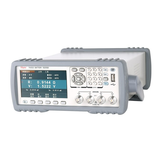
TH2523 Series Operation Manual Ver1.2 Chapter 2 Introduction to Front Panel and Operation This chapter will deal with basic operation procedures of TH2523. Before using the instrument, please read this chapter carefully. 2.1 Introduction to Front Panel Figure 2-1 shows the front panel of TH2523. TH2523 BATTERY TESTER PASS LOCK... -
Page 10: Introduction To Rear Panel
TH2523 Series Operation Manual Ver1.2 Press [SETUP] to enter into the MEAS SETUP page. Universal Arrow Keys There are four arrow keys: up, down, left and right arrow keys. Numeric Key This key is used to input the figure. LOCK Key Press this key to lock the screen and press it again to unlock the screen. - Page 11 TH2523 Series Operation Manual Ver1.2 WARNING TO AVOID ELECTRIC SHOCK, THE POWER CORD PROTECTIVE GROUNDING CONDUCTOR MUST BE CONNECTED TO GROUND. DISCONNECT POWER SUPPLY BEFORE HANDLER GPIB REPLACING FUSE. RATING FUSE 220V/50Hz 80VA T1AL 250V TRIGGER DEVICE RS-232C 贴标签 Figure 2-2 Rear Panel (1) GPIB Interface (Option) The GPIB interface is used to communicate with PC and further construct a GPIB test system.
-
Page 12: Display Zones
TH2523 Series Operation Manual Ver1.2 2.3 Display Zones TH2523 adopts 24 bits 4.3-inch LCD screen with a resolution of 480× 272. The display screen is divided into the following zones, as shown in figure 2-3. Figure 2-3 Display Zones Main Menu Indicate the name of the currently displayed page. -
Page 13: Keys And Their Corresponding Display
TH2523 Series Operation Manual Ver1.2 2.4 Keys and Their Corresponding Display Pages 2.4.1 Main Menu Key: [DISP] Press (DISP) to enter into display homepage. Selectable functions in this page are shown as follows: <MEAS DISP> <BIN DISP > <TRACE DISP> <STATI DISP>... - Page 14 TH2523 Series Operation Manual Ver1.2 Figure 2-4 TH2523 Boot Screen If the password protection is enabled, you will be asked to input your password. After inputting your password, press [ENTER] to enter into the main menu page. NOTE: The series of products have enabled password protection and the default password is 2523.
-
Page 15: Chapter 3 Basic Operations
TH2523 Series Operation Manual Ver1.2 Chapter 3 Basic Operations 3.1 <MEAS DISP> Press down [DISP], the <MEAS DISP> page will be displayed in the screen, as is shown in figure 3-1. Figure 3-1 Measurement Display The following measurement parameters can be set in this page. Measurement Function(FUNC R-X)... -
Page 16: Measurement Functions
TH2523 Series Operation Manual Ver1.2 The following information will be displayed in the display zone of measurement result/ conditions. These conditions can be set on pages of <MEAS SETUP> and <MEAS DISP>. Voltage/ current monitoring of DUT(Vm,Im). ON/OFF status indicator of the REL function. ( ON indicates that the current displayed ... -
Page 17: Meas Range
TH2523 Series Operation Manual Ver1.2 more 2/3 If the desired parameters are not displayed in this page, press more 2/3 to display them Z-θd Z –θr more 3/3 3.1.2 MEAS RANGE There are two options in MEAS RANGE, which can be selected according to the impedance and the DC voltage of DUT. -
Page 18: File Manage
TH2523 Series Operation Manual Ver1.2 Measurement delay time (a time starting from the measurement start-up to the measurement beginning) time showing measurement result Three measurement speeds are available: FAST (fast, approx. 50meas/ sec), MED (medium, approx. 10meas/ sec) and SLOW (slow, approx. 6.25meas/ sec). Operation procedures are as follows: The measurement result is displayed as a 5-digit number in the decimal point floating mode. -
Page 19: Bin Disp
TH2523 Series Operation Manual Ver1.2 SHORT operation: When this key is used for short clear, the test fixture must be shorted correctly, or it will result in relative data error and finally it will deviate from the accurate measurement result. The correct short connection is shown as follows. 3.2 <BIN DISP>... -
Page 20: Trace Disp
TH2523 Series Operation Manual Ver1.2 Figure 3-2 Bin Display Page Figure 3-3 Compare Display Page MODE: Compare and BIN. Compare: compare function of DUT; BIN: judgment of good or bad products. SOUND: NG, GD and OFF. NG: not good product sound; GD: good product sound; OFF: sound is off. -
Page 21: Meas Setup
TH2523 Series Operation Manual Ver1.2 Figure 3-4: Trace Display Page Move to TOOLS, the following items will be displayed in the soft key zone: SCAN START: Press [SCAN START], trace scanning will start; when [SCAN STOP] is displayed and press it, trace scanning will stop. TRACE A+B: Press this key, A+B, A, B will be alternately displayed. - Page 22 TH2523 Series Operation Manual Ver1.2 Figure 3-5 Measurement Setup Page The following items can be set in the <MEAS SETUP> page. FUNC R-X: Move the cursor to it, and then you can choose the desired parameters in the soft key zone. :AUTO : AUTO, HOLD, ▼, ▲...
-
Page 23: Trig
TH2523 Series Operation Manual Ver1.2 255, and then press X1 to finish inputting. Vm:OFF: Move the cursor to it, ON and OFF will be displayed in the soft key zone. The measurement voltage across DUT will be displayed in the <MEAS DISP> page when ON is selected;... -
Page 24: Delay
TH2523 Series Operation Manual Ver1.2 When Trig is set to the MAN mode, TH2523 will make a measurement by each press of [TRIG] button on the front panel. When Trig is set to the EXT mode, TH2523 will make a measurement at each time the HANDLER interface receives a trigger signal. -
Page 25: Trace Setup
TH2523 Series Operation Manual Ver1.2 Introduction to <BIN SETUP> MODE:Move the cursor to it, % and ABS will be displayed in the soft key zone. When % is selected, upper and lower limits will be displayed in the percentage error mode;... - Page 26 TH2523 Series Operation Manual Ver1.2 Figure 3-7 Trace Setup Page This page indicates the information about the discharge trace test of battery. It shows the discharging process of battery and displays measurement results of each time period in the trace form. This function can set the total time of monitoring, time interval between measurements and test point of auto stop.
-
Page 27: Statis Disp
TH2523 Series Operation Manual Ver1.2 corresponding soft key to confirm. When the primary measurement result is larger than the datum set in A Stop1 or less than the datum set in A Stop 2, the instrument will automatically stop testing. For the accuracy of measurement result, two more measurements will be done when the instrument finds the measurement result exceeding its range, and then TH2523 will stop testing. -
Page 28: Mode
TH2523 Series Operation Manual Ver1.2 Figure 3-8 Statistic Display Page The function of this page is to count measurement data, such as some engineering coefficients, the PASS/FAIL rate. In this page, it is also workable to analyze the average value of results for multiple measurements. -
Page 29: Statis A/Statis B
TH2523 Series Operation Manual Ver1.2 numerical keyboard. The instrument can make statistic analysis on up to 30,000 measurement results. 3.7.4 Statis A/Statis B Move the cursor to it and select through the soft key. When A is selected, TH2523 will compare the measurement result with the limit ranges of its primary parameter, count times of pass, times of higher and lower results;... -
Page 30: Tools
TH2523 Series Operation Manual Ver1.2 Hi Lo Hi Lo Corresponding formula: NOTE: Explanations for variables in formulas from 1) to 5) :The total measurement times that a sample is used to make statistic analysis, which corresponds to the value of TIMES. :Measurement results of each sample measurement. - Page 31 TH2523 Series Operation Manual Ver1.2 will be displayed in the corresponding zone (measurement times is the times set on the screen). Pressing STAT STOP will stop counting. TRIG:Trigger the instrument to make measurement operation.
-
Page 32: Chapter 4 System Setup And File Manage
TH2523 Series Operation Manual Ver1.2 Chapter 4 System Setup and File Manage 4.1 System Setup Press [SETUP] and then press SYSTEM SETUP in soft key area to enter into the <SYSTEM SETUP> page shown in the following figure 4-1. Figure 4-1 System Setup Page The following functions can be set in this page: Key Sound, Language, Password, Bus Mode, Baud Rate, Bus Addr, Date and Time. -
Page 33: Password
TH2523 Series Operation Manual Ver1.2 ENGLISH: Set the language as English. CHINESE: Set the language as Chinese. 4.1.3 Password Set the password protection function. OFF: Disable the password protection function. Before turning off the password protection function, you must input the original password. ON: Enable the password protection function. -
Page 34: Bus Addr
TH2523 Series Operation Manual Ver1.2 4.1.6 Bus Addr Bus address is used to control and display the current GPIB interface bus address. Move the cursor to BUS ADDR, the following items will be displayed in the soft key zone. INCR++ ... -
Page 35: Introduction To Save/Recall
TH2523 Series Operation Manual Ver1.2 4.2.1 Introduction to Save/Recall By the function of save/recall, user can save measurement results and configuration information to TH2523 internal Flash or external U disk; meanwhile user can recall data from TH2523 internal Flash or external U disk. Introduction to Methods and Applications of Save The table below shows the applicable save methods and applications: Table 4-1 Methods and Applications of Save... - Page 36 3. Before a U disk is connected to TH2523, you are recommended to save the data on it and Tonghui will not be liable for the data loss. 4. In order to rapidly save the instrument data to a U disk, it is not recommended to store too many files or folders.
- Page 37 TH2523 Series Operation Manual Ver1.2 FLASH and the external U disk. Press [Exit] to exit the file page. Figure 4-3 Internal file page 6 files’ information will be displayed in each internal file page or external file page, including file names and time of being saved. Operations of the internal file and the external file are similar.
- Page 38 TH2523 Series Operation Manual Ver1.2 this file. Copy to E: Press “Copy to E”. The instrument will copy the file the cursor locates or the selected file to a U disk. Delete Press “Delete”, if “YES” is selected, the instrument will delete the file that the cursor locates.
-
Page 39: Chapter 5 Performance Index
TH2523 Series Operation Manual Ver1.2 Chapter 5 Performance Index 5.1 Measurement Function 5.1.1 Measurement Parameters and Notations R:resistance V: DC voltage Z:impedance X:reactance C:capacitance L:inductance :phase angle (deg degree) Q:quality factor r: phase angle (rad radian) 5.1.2 Measurement Groups TH2523 has 11 measurement groups: R, R-V , V , R-Q , L-Q , L-R , R-X , C-D, Z-d, Z-r ,R-C. -
Page 40: Average
TH2523A: The maximum input voltage that the test terminal can withstand is 350V. 5.2.3 Maximum Display Range Parameter Measurement Display Range 0.2000nH to 1H 0.001mΩ to 3.5000kΩ R、X、Z 0.001 to 9999.9 -179.99° to 179.99° θ -3.1416 to 3.1416 V (TH2523/A) 0.0001V to 350.000V (TH2523A) -
Page 41: Measurement Accuracy
TH2523 Series Operation Manual Ver1.2 5.2.4 Measurement Accuracy Measurement accuracy depends on measurement stability, temperature coefficient, linearity, repeatability and correction interpolation error. Checking the measurement accuracy should be taken under the following circumstances: a. Warm-up time should be more than 30 minutes. b.... -
Page 42: Q Accuracy
TH2523 Series Operation Manual Ver1.2 FAST: (acquiring the basic accuracy at the temperature of 20 º C± 5 º C; the temperature coefficient plus ± 0.05%/ º C.) Model:TH2523 /TH2523A Display Digits: 4 Range |Maximum Resolution Measurement Accuracy for 6 Accuracy for one display value| constant current... -
Page 43: Accuracy
TH2523 Series Operation Manual Ver1.2 When Dx>0.1, D should be multiplied by (1+D 5.2.7 θ Accuracy The accuracy of θ is given by the formula below: Accuracy θe = [deg] 5.2.8 Basic Accuracy for Voltage Measurement SLOW, MED: (acquiring the basic accuracy at the temperature of 20 º C± 5 º C; the temperature coefficient plus ±... - Page 44 TH2523 Series Operation Manual Ver1.2 FAST: (acquiring the basic accuracy at the temperature of 20 º C± 5 º C; the temperature coefficient plus ± 0.005%/ º C.) Model: TH2523A Display digits: 4 Range |Maximum Resolution Accuracy for 6 months Accuracy for one year display value| 30 V...
-
Page 45: Chapter 6 Remote Control
TH2523 Series Operation Manual Ver1.2 Chapter 6 Remote Control 6.1 RS232C Connection RS-232 standard, also called as asynchronous serial communication standard, has already been widely used for data communication between computers, computer and external equipment. RS is the English abbreviation of Recommended Standard; 232, the standard number. This standard is issued by EIA in 1969, which rules to send one bit in a data line every time. -
Page 46: Gpib Bus (Option)
TH2523 Series Operation Manual Ver1.2 Figure 6-1 shows that the serial interface pin definition of this instrument is different from that of 9 pin connector used in computer. User can purchase the serial interface cable from our company. RS232 interface characterizes with a baud rate ranging from 9600 to 115200, no parity, 8-bit data bit, 1-bit stop bit. - Page 47 TH2523 Series Operation Manual Ver1.2 Figure 6-2 GPIB Connector/Pin Structure Figure 6-3 Typical GPIB System Interconnection for Double-piggyback Connector...
-
Page 48: Gpib Interface Functions
TH2523 Series Operation Manual Ver1.2 Figure 6-4 Typical GPIB System Interconnection for 4-piggyback Connector 6.2.1 GPIB Interface Functions The following cable shows the TH2523 GPIB interface functions: Code Capability Function Data Source Handshake Three-wire Shake Acceptor Handshake Three-wire Shake Basic Talker Transmit instrument data. -
Page 49: Gpib Addressing
TH2523 Series Operation Manual Ver1.2 Code Capability Function Device Trigger Transmit trigger signal. Control Transmit control data. Table 6-2 GPIB Interface Capabilities and Functions. 6.2.2 GPIB Addressing User can set the bus mode address of the GPIB parallel communication interface to a value from 1 to 31. -
Page 50: Scpi (Standard Commands For Programmable Instruments)
TH2523 Series Operation Manual Ver1.2 soon as TH2523 sends a SRQ service request signal, it will set the status byte to 6. 6 bytes are RQS request service bytes and sometimes connects with serial poll to act as the status byte. When TH2523 enables the SPOLL command, it will clear the RQS request service bit and the SRQ string. -
Page 51: Usbtmc Remote Control System
TH2523 Series Operation Manual Ver1.2 6.3 USBTMC Remote Control System USB (Universal Serial Bus) remote control system controls the instrument through the USB interface. This connection conforms to USBTMC-USB488 and USB2.0 protocols. 6.3.1 System Configuration Connect USB interfaces on PC and TH2523 through a USB cable. 6.3.2 Install the Driver When TH2523 is first connected to a PC through a USB cable, the prompt information –Found New Hardware will show on the right bottom of the computer desktop, as is shown below:... - Page 52 TH2523 Series Operation Manual Ver1.2 Figure 6-6 Procedure 2 of Installing USB Driver When the installation of driver is finished, user can see “usb test and measurement device” in the device manager of PC, as is shown in the following figure. Figure 6-7 USBTMC Display of PC Device Manager...
-
Page 53: Usbcdc Virtual Serial Port
TH2523 Series Operation Manual Ver1.2 When user is using USBTMC interface, labview software can be used to access the instrument. 6.4 USBCDC Virtual Serial Port When “USBCDC” is selected, the USB interface can be configured as a virtual serial port (VCom) Connect PC and TH2523 to the USB interface through a USB cable. -
Page 54: Chapter 7 Scpi Command Reference
TH2523 Series Operation Manual Ver1.2 Chapter 7 SCPI Command Reference 1. Data Conventions of This Manual NR1:integer, for example:123 NR2:fixed number, for example: 12.3 NR3:floating number, for example: 12.3E+5 NL:CR character,integer: 10 ^END:EOI (end) signal of IEEE-488 bus. 7.1 TH2523 Subsystem Commands ●DISPlay ●TRIGger ●COMParator... -
Page 55: Function Subsystem Commands
TH2523 Series Operation Manual Ver1.2 Functions of <page name> are as follows: Set the display page to the basic measurement. MEASurement Set the display page to bin comparator. BCOMP TSWEEP Set the display page to trace sweep. STATistics Set the display page to statistics. Set the display page to measurement setup. - Page 56 TH2523 Series Operation Manual Ver1.2 The :IMPedance command sets the “function” parameters. The FUNCtion:IMPedance? query returns the current “function” parameters. Command Syntax: FUNCtion:IMPedance <function>...
- Page 57 TH2523 Series Operation Manual Ver1.2 Details are as follows: Set “function” as R. Set “function” as V. Set “function” as R-V. Set “function” as R-Q. Set “function” as L-Q. Set “function” as L-R. Set “function” as R-X. Set “function” as Z-θ°. Set “function”...
- Page 58 TH2523 Series Operation Manual Ver1.2 The :IMPedance:RANGe:AUTO command sets the range auto selection mode. The FUNCtion:IMPedance:RANGe:AUTO? query returns the current range mode. Command syntax: ON (1) FUNCtion:IMPedance:RANGe:AUTO OFF (0) Where, Character 1 (integer:49) means ON. Character 0 (integer: 48) means OFF. For example: WrtCmd(“FUNC:IMP:RANG:AUTO ON”);...
- Page 59 TH2523 Series Operation Manual Ver1.2 Character 1 (integer:49) means ON. Character 0 (integer: 48) means OFF. For example: WrtCmd(“FUNC: VDC:RANG:AUTO ON”); Set the DC voltage range as auto. Query syntax: FUNCtion: DC voltage:RANGe:AUTO? Return format: <NR1><NL^END> The :Source MONitor:VAC command sets the voltage monitoring switch. The FUNCtion:SMONitor:VAC? query returns the current mode of the voltage monitoring switch.
- Page 60 TH2523 Series Operation Manual Ver1.2 Query syntax:FUNCtion:SMONitor:IAC? Return format:<NR1><NL^END> The :DEV<n>:MODE command sets the deviation measurement mode. The FUNCtion:DEV<n>:MODE? query returns the current mode of the deviation measurement. Command Syntax: ABSolute FUNCtion:DEV<n>:MODE PERCent Where: ABSolute Deviation display of absolute value PERCent Deviation display of percentage Directly display the real measurement value.
- Page 61 TH2523 Series Operation Manual Ver1.2 Query syntax: FUNCtion:DEV<n>:REFerence? Return format: <NR3><NL^END> The :DEV<n>:REFerence:FILL sets the nominal value of deviation. It controls the instrument to make a measurement and copies primary and secondary resluts as nominal value. Command syntax: FUNCtion:DEV<n>:REFerence:FILL Where, <n>...
-
Page 62: Aperture Subsystem Commands
TH2523 Series Operation Manual Ver1.2 Return: 50 the supply frequency is 50Hz 60 the supply frequency is 60Hz 7.1.3 APERture Subsystem Commands The APERture subsystem commands are mainly used to set the measurement speed and the average times used in measurement. The APERture? query returns the current measurement speed and average times used in measurement. - Page 63 TH2523 Series Operation Manual Ver1.2 TRIGger [:IMMediate] :SOURce INTernal EXTernal HOLD :DELay <value> The :IMMediate command triggers a measurement. Command syntax: TRIGger[:IMMediate] For example:WrtCmd(“TRIG”); The :SOURce command sets the mode of trigger source. The :SOURce? query returns the current mode of trigger source. Command syntax: INTernal TRIGger:SOURce...
-
Page 64: Fetch? Subsystem Commands
TH2523 Series Operation Manual Ver1.2 The :DELay command sets the delay time after triggering. The TRIGger:DELay? query returns the current delay time. Command syntax: <value> TRIGger:DELay Details are as follows: <value> In NR1, NR2 or NR3 data format ranging from 0S to 60S by a resolution of 1mS. - Page 65 TH2523 Series Operation Manual Ver1.2 The [:STATe] command sets the comparator function ON or OFF. The COMParator[:STATe]? query returns the current status of the comparator funciton. Command syntax: ON(1) COMParator[:STATe] OFF(2) Where, 1 (integer: 49) means ON. 0 (integer: 48) means OFF For example: WrtCmd(“COMP:STAT ON”) Query syntax: COMParator[:STATe]? Return format: <NR1><NL^END>...
-
Page 66: Binsetup Subsystem Commands
TH2523 Series Operation Manual Ver1.2 For example: WrtCmd(“COMParator: BEEper NG”) Query syntax: COMP:BEEPer? Return value: NG indicates fail beeper. GD indicates pass beeper. OFF indicates the beeper function is off. The [:CompMode] command sets the compare mode of the instrument. The COMParator[:CompMode]? query returns the current compare mode. - Page 67 TH2523 Series Operation Manual Ver1.2 Command Tree: The:BINSETup:BinMode command set the bin compare mode. The:BINSETup:BinMode? query returns the current compare mode. Command syntax: BINSETup:BinMode ABS PERcent absolute value mode PERcent percentage mode For example: WrtCmd(“BINSETup:BinMode ABS”) Query syntax: BINSETup:BinMode? Return value:<NR1><NL^END> <NR1>...
- Page 68 TH2523 Series Operation Manual Ver1.2 Return value: <NR1><NL^END> <NR1> is 0 (integer:48) means OFF (integer: 49) means ON The:BINSETup:COMPareB command secondary parameter ON/OFF. The:BINSETup:COMPareB? query returns the current status of secondary parameter. Command syntax: BINSETup:COMPareB ON(1) OFF(0) set the secondary parameter function as ON OFF set the secondary parameter as OFF For example: WrtCmd(“BINSET: COMPB ON”) Query syntax: BINSETup:COMPB?
-
Page 69: Statistical Subsystem Commands
TH2523 Series Operation Manual Ver1.2 Query syntax: BINSETup:NORmalB? Return value: <NR3><NL^END> <NR3> the secondary parameter The:BINSETup:BINA command set the upper and lower limit of the primary parameter. According to different modes, the upper and lower limit of absolute value or percentage can be set. - Page 70 TH2523 Series Operation Manual Ver1.2 The :STATIstics:STATe command sets the statistical function of primary parameter or secondary parameter to ON or OFF. Command syntax: : STATIstics:STATe <1,2,A or B> Where, 1(integer: 49)means A. 2(integer: 50)means B.
- Page 71 TH2523 Series Operation Manual Ver1.2 A set the statistical function of primary parameter to ON B set the statistical function of secondary parameter to ON Query syntax: :STATIstics:STATe? Response: <A or B> <NL^END> For example: Query::STATI:STAT? Response: A The :STATIstics:STATUS command sets the statistical function to ON or OFF. Command syntax: : STATIstics:STATUS ON(1) OFF(0) Where,...
- Page 72 TH2523 Series Operation Manual Ver1.2 OFF(0) command is used to disable statistic function. TRIG command is used to trigger the measurement. The : STATIstics:COUNt? query returns the statistical comparator result. Query syntax: : STATIstics: COUNt? Response: <HI counting (NR1)>, <IN counting (NR1)>, < LO counting (NR1)> For example: Query: STATI: COUNt? Response: 1516, 9310, 737 The : STATIstics:MEAN? query returns the average value of statistical results.
- Page 73 TH2523 Series Operation Manual Ver1.2 The : STATIstics:NORmalA command sets the nominal value of primary parameter in statistical function. Command syntax: STATIstics: NORmalA <value> For example: STATIstics: NORmalA 50 Set the nominal value of primary parameter to 50, the unit can be Ω or V according to the selected measurement parameter.
-
Page 74: Trace Subsystem Commands
TH2523 Series Operation Manual Ver1.2 Response: <Cp(NR2)>,<Cpk(NR2)> For example: Syntax: :STATI:CP? Response: 0.86, 0.14 7.1.9 TRACe Subsystem Commands The :TRACe:TOTAL <value> command is used to set and return the total time of scanning. For example: :TRACe:TOTAL Query syntax: :TRACe:TOTAL? Response: <value NR2> The TRACe:INTERval <value>... - Page 75 TH2523 Series Operation Manual Ver1.2 The :TRACe:AM<max value>, <min value> command is used to set the A Max value and the A Min value in trace scanning setting. For example: :TRACe:AM 3.1600E+03,2.0000E+02 Query syntax: :TRACe:AM? Response: <max value NR3>, <min value NR3> The :TRACe:BM<max value>, <min value>...
-
Page 76: System Subsystem Commands
TH2523 Series Operation Manual Ver1.2 :TRACe:SCAN? Response: STAR or STOP (STAR means the instrument is in the trace scanning mode while STOP means out of the trace scanning mode.) 7.1.10 SYSTem Subsystem Commands System subsystem commands are used for system setup. Command Tree: :SYSTem:BEEP OFF(0) ON (1) - Page 77 TH2523 Series Operation Manual Ver1.2 <value> The serial number of file ranging from 1 to 100 (NR1). For example: WrtCmd(“MMEM:LOAD:STAT 1”); The :STORe:STATe command saves the current settings into a file. Command syntax: MMEMory:STOR:STATe <value>,<name> Where, <value> The serial number of file ranging from 1 to 20 (NR1). <name>...
-
Page 78: Gpib Common Commands
TH2523 Series Operation Manual Ver1.2 7.2 GPIB Common Commands ●*RST ●*TRG ●*IDN ●*TST ●*ESE ●*SRE ●*ESR ●*STB ●*OPC ●*CLS The *RST command resets the instrument. Command syntax: *RST For example: WrtCmd(“*RST”); The *TRG command triggers the measurement and then sends the result to the output buffer. - Page 79 TH2523 Series Operation Manual Ver1.2 Descriptions for each byte of the standard event status register are shown as follows: Bit number Description Power On(PON) Bit User Request(URQ) Bit Command Error(EME) Bit Execution Error(EXE) Bit Device Dependent Error(DDE) Bit Query Error(QYE) Bit Request Control(RQC) Bit Operation Complete(OPC) Bit Query syntax: *ESE?
- Page 80 TH2523 Series Operation Manual Ver1.2 register. Descriptions for each bit of the standard event status register are shown as follows: Bit number Description Power On(PON) Bit User Request(URQ) Bit Command Error(EME) Bit Execution Error(EXE) Bit Device Dependent Error(DDE) Bit Query Error(QYE) Bit Request Control(RQC) Bit Operation Complete(OPC) Bit For example: WrtCmd(“*ESR?”);...
- Page 81 TH2523 Series Operation Manual Ver1.2 Return format:1<NL^END> Where, ASCII number 1(decimal number: 49) For example: WrtCmd(“*OPC?”)
-
Page 82: Chapter 8 Handler Interface
TH2523 Operation Manual Ver1.0 Chapter 8 Handler Interface TH2523 AC milliohmmeter equips with a Handler interface which is mainly used to output the sorting result. When the instrument is applied to an automatic component sorting test system, this interface will output the handshake signal and the sorting result output signal. The sorting result output corresponds to the comparison result output of the current comparator bin. - Page 83 TH2523 Operation Manual Ver1.0 effective. /PLO The main parameter is lower: the low bin comparison result output signal is effective. /PIN The main parameter PASS: the low bin comparison result output signal is effective. /SHI The secondary parameter is higher: the low bin comparison result output signal is effective.
- Page 84 TH2523 Operation Manual Ver1.0 EXTV1. Timing chart:...
-
Page 85: Chapter 9 Package Contents And Warranty
This warranty does not apply in the event of misuse or abuse of the product or as a result of unauthorized alterations or repairs. Tonghui will, without charge, repair or replace, at its option, defective product or component parts. - Page 86 TH2523 Operation Manual Ver1.0 The maintenance for this instrument should be performed by professional maintenance personnel. Do not substitute the internal components unauthorized when maintaining. In order to ensure the measurement accuracy, the instrument must be measured and corrected after maintenance. You should bear the maintenance expense for damages caused by unauthorized repairing or substituting components.
Need help?
Do you have a question about the TH2523/A and is the answer not in the manual?
Questions and answers