
Subscribe to Our Youtube Channel
Related Manuals for Tonghui TH2840 Series


Summary of Contents for Tonghui TH2840 Series
- Page 1 TH2840 Series Automatic Transformer Test System Changzhou Tonghui Electronic Co.,Ltd. www.tonghui.com.cn...
-
Page 2: Table Of Contents
Contents Chapter 1 Out of Box Audit ......................1 To Inspect the package ....................1 Power connection ......................1 Fuse ..........................1 Environment ......................... 1 Use of Test Fixture ....................... 2 Warm-up ........................2 Other features ....................... 2 Chapter 2 Introduction ........................ - Page 3 3.4.6 DC Bias ......................26 3.4.7 Level monitor function ..................27 3.4.8 Trigger ........................ 28 3.4.9 Average ......................29 3.4.10 Automatic level control ..................29 3.4.11 Source resistance ....................29 3.4.12 Deviation and reference ..................30 <Limit Setup> ......................30 3.5.1 Compare switch ....................
- Page 4 4.1.3 RS232 ......................... 46 4.1.4 LAN ........................47 4.1.5 Tools ........................48 <File> ......................... 49 4.2.1 U-disk manage performance ................50 4.2.2 Introduction to Store/Recall Function ..............50 4.2.3 Basic menu operation of file management ............51 4.2.4 Operation steps for file management ..............52 Chapter 5 Execute LCR measurement operation and some examples ........
- Page 5 HANDLER interface ....................70 7.5.1 Timing diagram of HANDLER signal ............... 70 7.5.2 Distribution and connection diagram for HANDLER........70 Example of transformer ....................71 Clear Settings ......................72 <Transformer ID> ...................... 72 7.8.1 Transformer ID ....................73 7.8.2 Primary Nums ....................73 7.8.3 Secondary Nums ....................
- Page 6 7.12.4 Pin Display Function for Stray Capacitance ............ 107 7.12.5 BAL Balance parameter display ............... 107 7.13 <File> page of Transformer Scan ................108 7.13.1 Transformer scan setup file (*.t40) ..............108 7.13.2 Operation steps for file manage ............... 109 7.13.3 Transformer deviation-deduction ..............
- Page 7 Measurement accuracy ..................... 121 8.3.1 Accuracy of│Z│,│Y│, L, C, R, X, G, B ............121 8.3.2 D accuracy ......................121 8.3.3 Q accuracy ......................122 8.3.4 Θ accuracy ......................122 8.3.5 G accuracy ......................122 8.3.6 Rp accuracy ...................... 122 8.3.7 Rs accuracy ......................
- Page 8 9.2.14 TRACE subsystem commands ................. 154 9.2.15 Handler subsystem commands ................. 157 9.2.16 FETCh? subsystem commands ................ 158 9.2.17 CORRection subsystem commands ..............160 9.2.18 Mass MEMory subsystem commands .............. 165 9.2.19 TRAN subsystem commands ................167 9.2.20 SYSTem system subsystem commands ............172 Modbus commands ....................
- Page 9 Announcement The description of the manual may not cover all contents of the instrument, and our company is subject to change and to improve the performance, function, inner structure, appearance, accessory and package of the instrument without notice. If there is puzzle caused by inconsistency of manual and instrument, then you can contact with our company by the address on the cover.
-
Page 10: Out Of Box Audit
Chapter 1 Out of Box Audit When you receive the instrument, some inspections are necessary, and the condition must be understood and available before installing the instrument. 1.1 To Inspect the package Inspect the shipping container for damage after unpacking it. It is not recommended to power on the instrument in the case of a damaged container. -
Page 11: Use Of Test Fixture
or where there is corrosive air. The normal working temperature is 0℃~40℃, relative humidity ≤75%, so the instrument should be used under above condition to guarantee the accuracy. There is heat abstractor on the rear panel to avoid the inner temperature rising. In order to keep good airiness, please don’t obstruct the left and right airiness holes to make the instrument maintain the accuracy. -
Page 12: Introduction
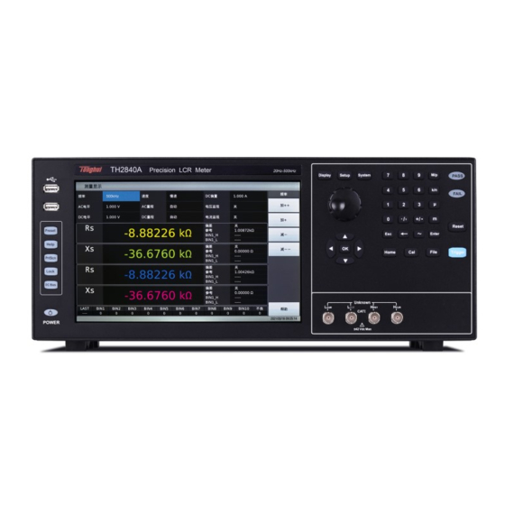
Chapter 2 Introduction In this chapter, the basic operation features of TH2840 series are described. Please read the content carefully before using TH2840X series instruments. 2.1 Introduction to front panel Figure 2-1 shows the front panel of TH2840 Series. 1 2 3 4... - Page 13 [Display] menu Press the [Display] key to enter the corresponding test display page of the meter function (bridge, transformer measurement, transformer scan, focus scan). [SETUP] menu Press the [Setup] key to enter the corresponding test setting page of the meter function (bridge, transformer measurement, transformer scan).
-
Page 14: Introduction To Rear Panel
2.2 Introduction to rear panel The rear panels of different models of TH2840 series are different. The detailed description of the rear panel layout of TH2840A, TH2840B, TH2840AX, TH2840BX will be introduced in 2.2.1 and the detailed description of the rear panel layout of TH2840NX will be introduced in 2.2.2. - Page 15 ! WARNING: ※ This instrument contains no operator serviceable parts inside; refer servicing to service trained personnel only. Rating Fuse 110V/60Hz 100VA T4AL 250V ※ Disconnect input power before replacing fuse 220V/50Hz 100VA T2AL 250V for continued fire protection, use manual specified type rating fuse only. RS-232C LCR Handler Trans Controller...
-
Page 16: Rear Panel Description 2
The Handler extension interface of transformer scanning. When the number of sorting signals of the transformer scanning Handler interface is insufficient, this interface can be used to expand the sorting signal and realize the sorting output of the transformer scanning result. 11) LCR HANDLER interface The Handler interface can realize the sorting output of the test results. -
Page 17: Introduction To Display Zone
6) LAN interface LAN interface is used to realize the control and the communication of network system. 7) USB Device interface The tester can communicate with PC through the USB Device interface. 8) Trans Handler interface The Handler interface of the transformer scan to realize the sorting output of the transformer scan results. -
Page 18: Main Menu Keys And Corresponding Displayed
The element composition of this page includes: title area, test condition area, 4 parameter result display area, sorting result display area, menu area, title area, status bar. 2.4 Main menu keys and corresponding displayed pages 2.4.1 [DISP] When the LCR function is used, press this key to enter into the LCR measurement display page. ... -
Page 19: System]
L, zero line N, ground line E should be the same as that of the instrument. TH2840 series instruments use soft switches. After plugging in the three-wire power supply, some indicators on the front panel will flash for a few seconds. After a few seconds, the power button will light up in red, and other buttons with LED indications will go out. - Page 20 Shutdown: After using the instrument, if you need to turn off the instrument, press and hold the power button at the lower left corner of the front panel to turn off the instrument. After turning off the instrument, the power button lights up in red, and the instrument is in the standby state. If you do not use the instrument for a long time, please disconnect the power cord and store the instrument in the environment required by 1.4.
-
Page 21: Description Of Lcr Function Module
Chapter 3 Description of LCR Function Module 3.1 <Meas Display> When the LCR function is applied, press [DISP], the <Meas Display> page will be displayed on screen as shown in the following figure. The element composition of this page includes: title area, test condition area, 4 parameter result display area, sorting result display area, menu area, title area, status bar. -
Page 22: Scaling Position
the menu to complete the function setting of the specified parameter. The menu display is shown in Figure 3-1-2: Figure 3-1-2 Parameter function setting 3.1.3 Scaling position Parameter setting attributes: enumerated type. The position of the decimal point has a direct relationship with the resolution of the result display, and the relative stability of the result can also be seen intuitively. -
Page 23: Result Display Of Bin Sort
Setting options: Menu options Function description Auto The default setting item, which automatically displays the position of the decimal point Used to fix the current decimal point position in the automatic state Increase+ Move the decimal point to the left Decrease- Move the decimal point to the right Note:... -
Page 24: Save The Bridge Test Results On The Usb Flash Drive
automatic test system through the HANDLER interface to realize the automatic sorting test. These limit settings can only be set on the <Limit Setup> page. Optional setting of comparison function: on or off (ON or OFF), the default state is: OFF. 3.1.4.2 Bin count function It is used to record and display the count value of each bin. -
Page 25: Usb Flash Drive Data Save
Figure 3-2-1 List display The P/F on the far right (representing PASS/FAIL) is used to indicate the comparison result of the current point: No comparison display: "---" PASS display: PASS (green) FAIL display: FAIL (red) 3.2.1 USB flash drive data save Use the USB flash drive to save the test results. -
Page 26: Trigger
Figure 3-3-1 Trace display In this display function page, each scan will perform automatic scan measurement of the tested component at 51, 101, 201, 401 or 801 point frequency in a linear or logarithmic manner with increasing conditions within the user preset mode range. Dynamic display of the response curve of the main and secondary parameters of the component under test with the change of the mode conditions on the LCD screen, the result of any point within the scanning range can be read on the screen. -
Page 27: Read
3.3.3 Read Condition setting for cursor reading Cursor: It is a red line. You can observe the test results of different parameters under the same scanning condition by turning the knob or moving the left and right keys. As shown in Figure 3-3-2: Figure 3-3-2 Read cursor display effect Value description: Read parameter... - Page 28 Figure 3-3-3 Curve button setting menu 3.3.4.1 Sweep point This parameter controls the number of points the instrument scans. That is, the number of points to be stepped within the start and end conditions. The system sets the number of measurement points in five groups: 51, 101, 201, 401, and 801.
-
Page 29: Usb Flash Drive Data Save
Figure 3-3-4 Display effect of 2-split screen Figure 3-3-5 Display effectof 4-split screen 3.3.5 USB flash drive data save Use the USB flash drive to save the test results. The test results and formats that can be saved are as follows: Time,pt ,x,P1,P2,P3,P4,COMP ----Respectively correspond to test time, point index, x-axis size, parameter 1~4 result... -
Page 30: Other Test Results
Figure 3-3-6 Save setting menu In the open state of continuous saving, the naming rule of the file name is trace + machine number + date, such as: trace-SN12345678- Single save, the naming rule of the file name is trace-trg + machine number + date, such as: ... -
Page 31: Test Function
Figure 3-4-1 Measurement setting 3.4.1 Test function Parameter setting attributes: enumerated type. The four parameters of the impedance element can be measured at the same time in one measurement cycle. The measurable parameters are as follows: Parameter Parameter Parameter Parameter name meaning name... -
Page 32: Frequency
3.4.2 Frequency Parameter setting attribute: numeric input. The maximum range of the test frequency of this series is from 20 Hz to 2 MHz, and the minimum resolution is: 0.001 Hz. Note: The specific models have different support range for the frequency. For details, please refer to the instrument selection guide. -
Page 33: Speed
Note: There is a linear constraint relationship of internal resistance between the voltage level and the current level. (For example, the current level corresponding to 30Ω internal resistance is 166.7μA ~ 66.67mA, and the current level corresponding to 100Ω internal resistance is 50μA ~ 100mA). -
Page 34: Range
Integration time (A/D conversion); Average times (the number of times used to obtain the average value of the continuous measurement results); Measurement delay (the time from start to start of measurement); Display time of measurement results; Generally speaking, when measuring slowly, the test result is more stable and accurate. You can choose FAST+, FAST, MED and SLOW 4 test speeds. -
Page 35: Level Monitor Function
The corresponding options and input ranges are as follows: Bias Source Bias Type Input Range Internal 100mA Voltage -40V~40V (Voltage, current, internal resistance are related to Ohm's Current -100mA~100mA law) Internal 2A Current 0~2A 0~120A Determined by External TH1778 Current external bias current source 3.4.6.2... -
Page 36: Trigger
The current monitoring value is displayed in the Im monitoring field on the <Meas Disp> page. Settable state: ON/OFF, respectively means to turn on/off the level monitoring function. Note: The calibration function of the instrument has an influence on the level monitoring function. Therefore, when the correction data changes, the level monitoring value also changes. -
Page 37: Average
When the instrument is triggered by the HANDLER interface, the trigger delay time can ensure reliable contact between the DUT and the test terminal. 3.4.8.3 Step delay Parameter setting attribute: numeric input. The step delay is the delay time from the output of the test signal to each measurement. The step delay time setting range is: 0 s to 60 s, and the minimum resolution is 1 ms. -
Page 38: Deviation And Reference
Deviation and reference 3.4.12 3.4.12.1 Deviation mode Parameter setting attributes: enumerated type. The deviation test function can make the deviation value (instead of real test value) be directly displayed on the screen. The deviation value is equivalent to the real test value subtracting the pre-set reference value. -
Page 39: Compare Switch
Figure 3-5-1 Limit setup The comparator function of the instrument can be set on this page. 10 bin limits can be set, and the measured results can be sorted into up to 11 bins (BIN1 to BIN10 and BIN OUT). Comparison ON/OFF (comparison function switch) Count ON/OFF (comparison count switch) Mode (comparison function limit mode) -
Page 40: Comparison Function Limit Mode
3.5.3 Comparison function limit mode The comparison function provides the following two parameter limit setting modes. As shown in Figure 3-3. 1) Tolerance mode In tolerance mode, set the deviation value from the nominal value (the nominal value is set in the nominal field) as the comparison limit value. -
Page 41: Bin Switch
3.5.6 BIN Switch Parameter setting attributes: enumerated type. Set the independent comparison switch of the specific sorting BIN: Setting Item Meaning description Turn off the comparison function of the specified BIN Turn on the comparison function of the specified BIN When the corresponding sorting BIN is OFF, the sorting process will skip this sorting limit comparison. -
Page 42: Total Point
Sweep condition (frequency [Hz], level [V], level [I], bias [V], bias [I]) Parameter function High/low limit (HIGH, LOW) Single point delay (DELAY[s]) 3.6.1 Total Point Set the number of points to be scanned for list sweep, the value range is 1~201; Parameter setting attributes: enumerated type. -
Page 43: Parameter Function
3.6.5 Parameter function 4 parameter functions, all of which can be set independently, and can also be quickly set to make one of the conditions relatively consistent; Figure 3-6-2 List parameter display menu 3.6.6 High/low limit The upper and lower limits of the parameters can be set independently, and can also be set quickly to make the settings have a certain relationship. -
Page 44: Common Test Conditions
Figure 3-7-1 Trace Setup This display function page is used to complete the setting of trace sweep measurement parameters, including split, sweep point, sweep type, start condition, stop condition, trace mode, X Format, Max-Min switch, 4 parameters, and Y display range, etc. 3.7.1 Common test conditions Frequency, level, speed, range, offset, trigger, delay, etc. -
Page 45: Sweep Point
3.7.4 Sweep point Here is the number of points to be scanned. There are five groups of 51, 101, 201, 401, 801 to choose from. 3.7.5 Sweep Type The sweep type is mainly used to set the conditions of the trace sweep, that is, to plot the test results according to the selected condition parameters, so it involves the type of condition parameters, the start size and the stop size of the condition change. -
Page 46: Max-Min
manner with the base 10 in the start and stop ranges Note: The log mode is only valid in the case of sweeping frequency. 3.7.8 Max-Min Set ON or OFF: Display the maximum and minimum values of the parameter curve results Do not display the maximum and minimum values of the parameter curve results 3.7.9 Ordinate range setting... -
Page 47: Open
Two correction methods are provided: Correction mode Description Full frequency correction Use insertion method to execute open and short correction of all frequency points Point frequency correction Execute open, short and load correction of the current set frequency point The following measurement control parameter setting domains can be set on the <User Corr> page. Open circuit correction (Open), short circuit correction (Short), load correction (Load), cable length selection (Cable), Load type, point frequency correction switch, reference value, etc. -
Page 48: Short
Operation steps of open correction function: Open correction includes full frequency open correction using interpolation calculation method and single frequency open correction for the set frequency point. Carry out the following steps to perform open correction for full frequency using the insertion calculation method. For details about single-frequency open correction, please refer to the "Load Correction"... -
Page 49: Load
following fixed frequency points. In addition to the following frequency points, based on the short-circuit correction data at the following frequency points, the instrument can calculate all short correction data of different test ranges which corresponds to all test frequencies by using the interpolation calculation method. -
Page 50: Load Type
frequency point and the standard reference value to eliminate other test errors. It can be seen that open circuit, short circuit and load correction can be performed at the set frequency point. Before setting the standard reference value, the reference value must be set in the reference value corresponding field. - Page 51 Short Perform a short correction test on the current frequency. Load Perform a load correction test on the current frequency. 3.8.6.1 Steps of load correction 1. Move the cursor to the Freq setting area, and set the frequency to be calibrated. 2.
-
Page 52: System And File
Chapter 4 System and File 4.1 <System Setup> Press the menu key [System] to enter the <System Setup> page. As shown in Figure 4-1-1: Figure 4-1-1 System Setup 4.1.1 Mode Setup 4.1.1.1 Bus Mode The bus mode is used to select the communication mode of the instrument. The options are as follows: AUTO Automatically select the RS232/LAN/USB... -
Page 53: User Setup
4.1.2 User Setup 4.1.2.1 Key Sound Parameter type: enumerated Parameter option Description Turn off the key sound. Turn on the key sound. 4.1.2.2 Pass Sound Parameter type: enumerated Parameter function: This area is used to control and display the sound mode when the measurement comparison result of the instrument is qualified. -
Page 54: Rs232
English Choose English operating language Chinese Choose Chinese operating language 4.1.2.5 Password Parameter type: enumerated type + input type Parameter function: This area shows the current password protection mode. Parameter Description operation options Turn off the password protection Lock system Open the password protection, including file protection and power-on password Lock file... -
Page 55: Lan
4.1.3.2 Address Parameter type: input type Parameter function: used to control and display the RS485, GPIB interface and Modbus bus address of the current instrument. Value range: 1~32 4.1.3.3 Cmd mode Parameter type: enumerated Parameter function: command mode can be set with SCPI command and ModeBus command protocol. -
Page 56: Tools
4.1.5 Tools 4.1.5.1 Preset For the convenience of customers, the instrument can be initialized to a known unified initial state. Standardize initial software operation design . In order to solve the problem of inconsistent setting status when the instrument leaves the factory. English menu Description Command... -
Page 57: File
Figure 4-1-2 Upgrade menu The dynamic prompt window of one-click upgrade is shown in Figure 4-1-3: Figure 4-1-3 Upgrade waiting prompt 4.2 <File> Because this series is equipped with an embedded system, it is very convenient to store the parameters set by the user in the form of a file in the system internal or external U disk. When the same settings are to be used next time, the user does not need to reset these parameters , Just load the corresponding file, you can get the last set parameters. -
Page 58: U-Disk Manage Performance
4.2.1 U-disk manage performance As mentioned above, this series is equipped with a USB HOST interface as standard, and an external USB flash drive can be used as a storage medium, thus breaking the limitation of the internal storage size of the instrument. You can also copy these files to an IBM PC with a USB interface or a desktop computer or Notebook computers compatible with it, so as to achieve unlimited expansion. -
Page 59: Basic Menu Operation Of File Management
the instrument Transformer single *.trt Save instrument's group setting file transformer single-group test configuration status Transformer sweep *.t40 Save instrument's setting file transformer sweep test configuration status Screenshot save *.png Save a screenshot of the instrument Test data *.csv Save test data Table 4-1 Storage methods and uses 4.2.3 Basic menu operation of file management The various operations on the file are as follows:... -
Page 60: Operation Steps For File Management
When the cursor is under the path corresponding to usb, copy the file or folder corresponding to the Delete Load Load the setting file specified by the file index to reconfigure the parameter settings of the Rename Rename the name of the file or folder at the cursor position;... - Page 61 name suffix is automatically generated, and there is no need to input the suffix; After the input is confirmed, a named setting file will be generated in the current directory. 4.2.4.2 File load When the cursor moves to the file type that can be loaded, the menu is displayed as above. Move the cursor to the location of the file to be loaded in the file list.
-
Page 62: Execute Lcr Measurement Operation And Some Examples
Chapter 5 Execute LCR measurement operation and some examples 5.1 Correction operation To execute correction operation (in order to prevent the stray impedance from affecting the test accuracy, it is necessary to make open/short correction), users can select one of the two correction modes. -
Page 63: Correct Connection Of Dut
Insert the short plate (TH26010) to the test fixture. Press MEAS SHORT to execute short correction. 5.2 Correct connection of DUT The instrument has H (current sampling high end Hc), L (current sampling low end Lc), H (voltage sampling high end Hp), L (voltage sampling low end Lp) and a total of four pairs of test terminals corresponding to the shielding end of each test terminal. -
Page 64: Eliminate The Influence Of Stray Impedance
5.3 Eliminate the influence of stray impedance Shielding ground Test terminal Metal conductor Figure 5-1 Influence of stray capacitance Shielding ground Shielding plate Test terminal Metal conductor Figure 5-2 Eliminate the influence of stray capacitance When the DUT has high impedance(such as small capacitance), the influence of stray capacitance cannot be ignored. -
Page 65: Operation Example For Testing Inductance
this way, the magnetic fields produced by these currents can be mutually offset and further eliminate the influence of mutual inductance coupling on test results. 5.4 Operation example for testing inductance 5.4.1 Test Condition Function: Ls-Q Frequency: 5.5kHz Level: 1.5Vrms Internal impedance: 100Ω... -
Page 66: Operation Example Of Testing Capacitance By Multi-Frequency List Sweep
If the test result is obviously incorrect, please check the following items. Check the tested inductance is in good connection with the test fixture or not. Check the test fixture is in good connection with the test terminals of the instrument or not. Redo the open/short correction. - Page 67 5.5.2.1 Set basic parameters Press [Display] to enter into the <Meas Display> page. The Parameter zone is currently displayed as Cp, D and the Level zone is 1.000V. Press [Setup] to enter into the <Meas Setup> page, meanwhile the following soft keys will be displayed in the soft key zone: Meas Setup, User Corr, Limit Setup, List Setup and File.
-
Page 68: Operation Example Of Load Correction
5.6 Operation example of load correction 5.6.1 Operation steps Assume that the test conditions used by the user are as follows: Frequency: 100kHz. Cp standard value: 11nF D standard value: 0.0005 Press [Cal], the instrument will display the <User Corr> page. Move the cursor to Load, the following soft keys will be displayed in the soft key zone: ON and OFF. -
Page 69: Transformer Single-Machine Test
Chapter 6 Transformer Single-machine Test 6.1 Circuit for transformer single-machine test 6.1.1 Some parameters of transformer 6.1.2 Transformer single test circuit and TURN test SEC+ SEC- TH2818 Nsp = U2 / U1 On TH2840X, TURN test has 4 display modes: Ns: Np =U2/U1 ... -
Page 70: Transformer Leakage Inductance Test
Due to the influence of output internal resistance (30, 100), when the primary inductance is too small, the distributed voltage signal is small and the transformer gets weak energy. As the test cable and relay will attenuate some energy, the stability and the accuracy of test will be affected. -
Page 71: Transformer Single Setup
6.2 <Transformer Single Setup> Press the shortcut key [Home] to enter the function selection interface, as shown in Figure 6-1-1. Figure 6-1-1 Single Setup Move the cursor to the Single Setup area or directly touch the single group setting area to enter the <Single Setup>... -
Page 72: Rsou
6.2.4 Rsou Move the cursor to the Rsou field, and the menu area on the right side of the screen will display: 100 Ω and 30 Ω. Click the "100 Ω" area, the internal resistance area will display "100 Ω", which means the output impedance of the instrument is 100 Ω, click the "30Ω"... -
Page 73: Single Display
frequency, level, other, deviation, nominal value, lower limit, upper limit, delay, average, and measurement. The parameter column is to select the parameter that needs to be measured. Move the cursor to the parameter column in each row. There are 16 measurement parameters for selection, namely Ls, Lp, Lk, Cs, Cp, Zx, Rs, Rp, Rd, D, Q, dZ, Ns, Ns:Np, Np, Np:Ns. -
Page 74: Save The Test Results Of A Single Set Of Transformers On The Usb Flash Drive
6.3.1 Save the test results of a single set of transformers on the USB flash drive Use the USB flash drive to save the test results. The test results and formats that can be saved are as follows: Time, pt, para, val, COMP ----Respectively correspond to test time, point index, parameter name, parameter result, comparison result. -
Page 75: Transformer Auto Scanning Test
Chapter 7 Transformer Auto Scanning Test 7.1 Introduction to scan test function TH2840NX can rely on an internal scan board or use an external TH1901/TH1806/TH1831 transformer scan box to form a transformer automatic test system; TH2840AX/TH2840BX can only use an external scan box to form a test system (no internal scan board). Note: If there is no functional difference, TH2840X will be used to replace the above three model descriptions. -
Page 76: Front Panel Of Scanning Box
Test fixture Scanning box Host Control cable If it is necessary to use the foot switch, connect the foot switch to the FOOT.C interface on the rear panel of Test Fixture. NOTE: Once the foot switch is used, the START button on the Test Fixture will not work. If the scanning box is TH1901A, user should connect the trachea to the valve controller. - Page 77 TONGHUI TH1901A TRANSFORMER TEST FIXTURE ELECTRONICS 测 试 夹 具 对 应 脚 位 GOOD 2 3 4 5 6 7 8 9 WARNING: ※ Mold the pins of transformers before measurement; ※ Clean the fixture in time for accurate measurement;...
-
Page 78: Rear Panel Of Scanning Box
11) Fixture pin number. In above figure, 1~20/24 is the corresponding pin number. 7.4 Rear panel of scanning box TEST LINE CYLINDER FOOT.C SCANNER HANDLER GO NG S R Introduction to each number on the lower panel TEST LINE: inlet port of the test cable, TH1901L 6-terminal test box is connected to inner part of TH1901A/B through this line. -
Page 79: Example Of Transformer
7.6 Example of transformer In order to understand the operation of transformer scanning test, the setting figures listed in the following chapters are based on the sample below. The detailed information will be described in latter sections. -
Page 80: Clear Settings
7.7 Clear Settings Before starting a new transformer ID test condition setting, the user must execute the Clear Settings to clear the unpredictable data that may exist in the memory of the instrument and prevent unpredictable errors during the test of the newly set test condition. The execution method is as follows: On any transformer sweep function page, press the button Preset on the left side of the front panel to select the function Clear Settings. -
Page 81: Transformer Id
7.8.1 Transformer ID You can input the transformer ID to be tested in this area. The setting method is as follows: Press the menu function Input, select the desired character in the soft keyboard, press Esc to cancel, press Enter to apply the entered transformer ID. Primary Nums 7.8.2 You can input the number of transformer primary groups in this area. -
Page 82: Fail Rescan
for users to view. Judgement result mode: It means that the test data of each parameter is displayed one by one during the scanning process, and the total PASS/FAIL is displayed in large characters after it is finished. Fail list: It means that the test data of each parameter is displayed one by one during the scanning process, and the unqualified parameters and their limit settings are displayed in the center of the screen after it is finished. -
Page 83: Cylinder Ctrl
Delay range: 0~60s; 0 means no delay. The maximum test delay is 60 seconds. Cylinder Ctrl 7.8.10 This area is used to set the switch of cylinder 24V power. ON: Output of 24V cylinder power is allowed during scanning. OFF: Output of 24V cylinder power is forbidden during scanning. FAIL HOLD: the test is stopped when a defective product is encountered during scanning. -
Page 84: Trans Pin To Fixture
Trans Pin To Fixture On the <Trans ID> page, press the menu key Trans Pin, it will jump to the <Trans Pin To Fixture> page. This page is used to connect the pin of the transformer to the pin of the test fixture, and to convert the pin number into a custom pin label. -
Page 85: Pin Label Setup
7.9.2 Pin Label Setup The transformer pin label function can convert the transformer pin that was originally only represented by numbers into the transformer pin represented by custom numbers or letters. As shown below: After setting the transformer pin label and related test conditions, it can be displayed in the PIN (pin) column in the transformer test interface as a custom transformer pin label (to be updated). -
Page 86: Trans Pin Setup
Trans Pin Setup 7.10.1 The following is the pin setting screen of PRI: A1 (PRI: A1 is used for Np1 as the primary winding): The following is the pin setting screen of PRI: A2 (PRI: A2 is used for Np2 as the primary winding):... -
Page 87: Series Pins Setup
Series Pins Setup 7.10.2 Before setting the transformer series pin, you need to confirm the parameters of the series test. For example, the Lx inductance needs to set the series pin. You can select the function Lx in the parameter menu bar, and then input the series pin. The above is: the short-circuit pin setting when series transformers Ns1 and Ns2 test Lx. -
Page 88: Trans Condition
The above is: Above figure shows the short pin setup of the "+" and "-" terminal when example parallel transformers Ns1 and Ns2 tests. 7.11 <Trans Condition> This page contains two tables: The table above is the parameter test condition table, which is mainly used to set the parameters and test conditions of the transformer under test. -
Page 89: Frequency, Voltage, Switch And Scanning Sequence
Frequency, voltage, switch and scanning sequence 7.11.1 There are multiple parameter variables corresponding to each parameter: frequency, level, deviation, average, delay, equivalence, scan sequence and switch. Touch or move the cursor to the corresponding setting area and modify the corresponding parameters according to the menu prompts to meet user needs. - Page 90 7.11.2.1 Turn Mode When touching the TURN setting area or moving the cursor to the TURN setting area, the TURN mode can be set in the menu on the right. TH2840X test TURN can choose the following 8 modes: TURN_v= primary standard value * secondary voltage/ primary voltage. This mode is ...
- Page 91 7.11.2.2 Turn Limits Setup The turns ratio limit setting table is used to set the nominal value, upper and lower limits, phase and short-circuit pins of each winding of the transformer. Touch the TURN limit setting table, or move the cursor to the TURN limit setting area, and use the number keys, the corresponding magnification or the [ENTER] key to set.
-
Page 92: Lx Test Conditions Setup
7.11.2.4 TURN Turn-Ratio Short Pins When setting the turns ratio short pins, you can use the soft key. and ~ to input multiple pins, the maximum number of pins can be saved here is 48. Example: 1: Input a discontinuous number "1, 3, 5, 7, 9" and use the soft key. to separate each number, press ENTER to confirm, the final data displayed in the table is (1, 3, 5, 7, 9). - Page 93 7.11.3.1 Lx Limit Setup The Lx limit setting table is used to set the Lx standard value, upper and lower limits, bias, multi-frequency, multi-level, Q standard value and Q upper and lower limits of each transformer winding. Touch the Lx limit setting table, or move the cursor to the Lx limit setting area, and use the number keys, the corresponding magnification or the [ENTER] key to set.
- Page 94 7.11.3.3 Lx Multi-frequency Setup If the user needs to use different frequencies to test different Lx pins of the transformer, in the transformer Lx limit setting table, touch or move the cursor to the Lx frequency area. After inputting the frequency in this area, the frequency here will be automatically used during the test. If the parameter is not set, the frequency of Lx in the test condition table will be used.
-
Page 95: Lk Test Conditions Setup
7.11.3.5 Q Limit Setup On the <Trans Condition> page, touch or move the cursor to the Q-STD, Q-Low and Q-High to set. Note: The Q value test switch is set at the Lx switch. Lk Test Conditions Setup 7.11.4 On the <Trans Condition> page, touch or move the cursor to the Lk column of the test condition table to set the Lk parameters. - Page 96 7.11.4.1 Lk Limit Setup The Lk limit setting table is used to set the Lk standard value, upper and lower limits, multi-frequency, multi-level, and short-circuit pins of each winding of the transformer. Touch the Lk limit setting table, or move the cursor to the Lk limit setting area, and use the number keys, the corresponding magnification or the [ENTER] key to set.
- Page 97 7.11.4.3 Lx multi-level Setup If the user needs to use different levels to test different Lk pins of the transformer, in the transformer Lk limit setting table, touch or move the cursor to the Lk level area. After inputting the level in this area, the test will automatically use here.
-
Page 98: Cx Test Conditions Setup
the pins will be ignored. 3: Input part of continuous numbers and non-continuous numbers "1,2,3,4,5,7,9", the continuous part is the same as step 2, the discontinuous part is the same as step 1, press ENTER to confirm, and finally displayed in the table The data is (1~5,7,9). Cx Test Conditions Setup 7.11.5 On the <Trans Condition>... - Page 99 The Cx limit setting table is used to set the positive and negative pins of Cx, short pins, nominal value, upper and lower limit, multi-frequency, multi-level, and D value limit. Due to the large number of table parameters, one page cannot display all the setting parameters. Here, you can move the cursor left and right, or directly swipe the limit setting table on the screen to display the incomplete parameter settings.
- Page 100 ignored. 3: Input part of consecutive numbers and non-consecutive numbers "1, 2, 3, 4, 5, 7, 9", the continuous part is the same as step 2, the non-consecutive part is the same as step 1, press the ENTER key to confirm, and finally display in the table The data is (1~5, 7, 9). 7.11.5.3 Cx Multi-frequency Setup If the user needs to use different frequencies to test different Cx pins of the transformer, in the transformer Cx limit setting table, touch or move the cursor to the frequency area of Cx, after...
-
Page 101: Zx Test Conditions Setup
7.11.5.5 D Limit Setup In the transformer Cx limit setting table, touch or move the cursor to D-Std, D-Low and D-High of Cx to set. NOTE: The D value test switch is set at the Cx switch. Zx Test Conditions Setup 7.11.6 On the <Trans Condition>... - Page 102 7.11.6.1 Zx Limit Setup The Zx limit setting table is used to set the Zx standard value, upper and lower limit, bias, multi-frequency and multi-level. Touch the Zx limit setting table, or move the cursor to the Zx limit setting area, and use the numeric keys, corresponding magnification or [ENTER] key to set.
- Page 103 7.11.6.3 Zx Multi-frequency Setup If the user needs to use different frequencies to test different Zx pins of the transformer, in the transformer Zx limit setting table, touch or move the cursor to the frequency area of Zx, after inputting the frequency in this area, the frequency here will be used automatically during the test. If the parameter is not set, the frequency of Zx in the test condition table will be used.
-
Page 104: Acr Test Conditions Setup
ACR Test Conditions Setup 7.11.7 On the <Trans Condition> page of the transformer scan, touch or move the cursor to a column of ACR in the test condition table to set the ACR parameters. 7.11.7.1 ACR Limit Setup The ACR limit setting table is used to set the standard value, upper and lower limit, multi-frequency and multi-level of ACR. - Page 105 7.11.7.2 ACR Multi-frequency Setup If the user needs to use different frequencies to test different ACR pins of the transformer, in the transformer ACR limit setting table, touch or move the cursor to the frequency area of ACR, after inputting the frequency in this area, the frequency here will be used automatically during the test. If the parameter is not set, the frequency of the ACR in the test condition table will be used.
-
Page 106: Dcr Test Conditions Setup
DCR Test Conditions Setup 7.11.8 On the <Trans Condition> page of the transformer scan, touch or move the cursor to a column of DCR in the test condition table to set DCR parameters. 7.11.8.1 DCR Limit Setup The DCR limit setting table is used to set the standard value, upper and lower limit of DCR. Touch the DCR limit setting table, or move the cursor to the DCR limit setting area, and use the numeric keys, corresponding magnification or [ENTER] key to set. -
Page 107: Ps Test Conditions Setup
PS Test Conditions Setup 7.11.9 On the <Trans Condition> page of the transformer scan, touch or move the cursor to a column of PS in the test condition table to set PS parameters. 7.11.9.1 PS Limit Setup The PS limit setting table is used to set the positive and negative pins and upper and lower limits of Touch the PS limit setting table, or move the cursor to the PS limit setting area, and use the numeric keys, corresponding magnification or [ENTER] key to set. - Page 108 7.11.9.2 PS Test Pin Setup This page is used to set the shorted pins. In the process of auto scanning test, the instrument will test DCR of each set pin and make comparison with the PS low limit set on PS limit setup page. The following figure shows the example transformer and its setup page of pin short test.
-
Page 109: Bl Test Conditions Setup
7.11.10 BL Test Conditions Setup On the <Trans Condition> page of the transformer scan, touch or move the cursor to a column of BAL in the test condition table to set BAL parameters. 7.11.10.1 BL Test Setup BAL (balance) is a parameter used to compare the consistency of the two windings of a transformer. BAL upper and lower limits, balance windings, absolute values, and balance formulas can be set. - Page 110 7.11.10.2 BAL Absolute Value Setup In the formula used to judge the balance of the two windings, to set whether the final result is compared with the absolute value. For example, the formula Lx1-Lx2: When the absolute value switch is ON, the formula will be converted to |Lx1-Lx2|, and the result will be the absolute value of Lx1-Lx2 compared with the set upper and lower limits;...
-
Page 111: Handler Mode Function
7.11.11 Handler Mode Function After a scan test, the Handler outputs the final sorting signal according to the settings here. There are currently three sorting modes: default, X30, X12. 1. Default: output unqualified signals according to the parameters shown in the signal column in the table. -
Page 112: Trans Scan
The page states the following: [Pass] indicates the pass times of each parameter of L.K.~DCR. [Pass]+[Whole]: In one measurement, all parameters that need to be measured in L.K.~DCR are qualified, then [Pass] corresponds to the value of [Whole] (total qualified column) plus 1. [Fail] Indicates the fail times of each parameter of L.K.~DCR. -
Page 113: Each Display Zone Under This Page
Each Display Zone under this page 7.12.1 PIN Area: the area below the column displays the pins of each winding, but the pins of Cx are not displayed in this area. When you need to check, you can press the [DISPLAY] key, and the pins will be displayed in the cell of the test result (Only the 1st of the positive and negative pins is displayed). -
Page 114: Pri Page-Turning Function
At this time, put an open-circuit transformer sample with the same pin position as the product under test on the test fixture, and then press the soft key Meas Open, and the instrument will perform an open-circuit scan correction on the test fixture. This function can improve the test accuracy of small inter-turn capacitance and large inductance (>300mH level), and can also improve the open circuit value of DCR and PS. -
Page 115: Pin Display Function For Stray Capacitance
Pin Display Function for Stray Capacitance 7.12.4 After testing the stray capacitance, press the Display key to view some pins of the current stray capacitance. 7.12.5 BAL Balance parameter display After the scan is over, press the Display key to switch to display the result value between the two windings of the BAL. -
Page 116: File> Page Of Transformer Scan
7.13 <File> page of Transformer Scan Transformer scan setup file (*.t40) 7.13.1 The internal space of the instrument can save a certain number of scan setting files (*.t40 files), the number is determined by the remaining internal storage space, and the scan setting files can also be displayed/operated through an external storage USB flash drive, and supports large-capacity USB flash drives (FAT32 format) read and write functions. -
Page 117: Operation Steps For File Manage
Operation steps for file manage 7.13.2 View existing files. Click the [+] before the folder icon, or click the folder and right-click to view all the files in this folder. Files saved in the root directory can be viewed directly by turning the knob counterclockwise. Follow the steps below to save control setup parameters to a file. -
Page 118: Focus
According to the set method, enter <Trans Scan> page after setting parameter. Put standard transformer to test fixture and lock it, press [START] in scan box for several times to get a stable test value; Press [Deviation] to enter <Trans Deviation> page; the figure is as below: Set [Deviation] as ON ;... -
Page 119: Split
On the Trans Scan page, turn on the Focus switch, and then click the parameter you want to test repeatedly. Click on the cell, when its background turns blue, it is in the selected state, at this time, press the Trigger key to measure the data of this cell;... -
Page 120: Frequently Asked Questions And Answers In Transformer Scan Test
same time, the split function can be switched to meet the test requirements. Split functions are 2-1, 3-1, 4-1, 2-2, 3-2, 4-2. The default is 2-1. If the table does not display all parameters, you can touch the corresponding table and slide left and right to view it, or press the left and right soft keys to view it directly. -
Page 121: Measurement Interruption
meanwhile, “Ignore std test” is set as “FORCE DEV” on [Trans ID]. Solution:1. Set “Ignore std.” as “FORCE TEST”. 2. Set standard value on parameter limit setup menu. Measurement interruption 7.16.3 In the process of test, user finds the instrument only tests the test parameter in the first several groups of value, but the last ones has not been tested. -
Page 122: Unstable Turn
Unstable TURN 7.16.7 For the transformer with high magnetic permeability magnetic-core,test winding will be unstable. Solution: 1. Use the TURN_V mode to test winding (voltage-turn mode). 2. Use deviation deduction. Difference between the first and the second Lx 7.16.8 Because the transformer, with high magnetic permeability magnetic-core, is polarized in the test of DCR or TURN, the test results of the first and the second Lx test will be quite different. -
Page 123: Use Th1801-Ext2A-Out To Make Test Fixture
7.17.1 Use TH1801-EXT2A-OUT to make test fixture User should buy the TH1801-EXT2A extension ground board from our company. The figure below also shows the connection of using 2 spring thimble to make test probe. Double-row pin, which can be inserted into the relay board of the scan box. - Page 124 The theory of 4-cable measurement is the test cable of DRIVE and SENSE should be divided. In this figure1D means the drive terminal of pin1, 1S means sense terminal of pin 1.
-
Page 125: Performance And Test
Chapter 8 Performance and Test 8.1 Test function 8.1.1 Parameter and symbol 8.1.1.1 LCR Module Parameter Parameter Parameter Parameter name meaning name meaning Equivalent parallel Equivalent series capacitance capacitance Equivalent parallel Equivalent series inductance inductance Equivalent parallel Equivalent series resistance resistance Conductance Susceptance... -
Page 126: Test Combination
Secondary turn Ns:Np Secondary turn /primary turn Primary turn Np:Ns Primary turn /secondary turn 8.1.1.3 Transformer Scan Test combination 8.1.2 Four parameters can be selected arbitrarily, regardless of primary and secondary parameters. Mathematical operation 8.1.3 Operation between the measurement value and the programmable nominal value: absolute deviation ∆ABS and percent deviation ∆%. -
Page 127: Connection Modes Of Test Terminals
Connection modes of test terminals 8.1.8 TH2840X adopts 4-terminal test method. Hcur: current sample high terminal Lcur: Current sample low terminal Hpot:voltage sample high terminal Lpot: Voltage sample low terminal Test speed (Frequency>=10kHz) 8.1.9 Fast+:about 1800 times/s(0.55ms/time) Fast:about 300 times/s(3.3ms/time) Medium:about 11 times/s(90ms/time)... -
Page 128: Test Signal Level
Test signal level 8.2.3 Mode Range Accuracy Resolution Normal —2V ±(10%×preset value+2mV) Voltage constant 10mV —1V ±(6%×preset value+2mV) 100μV level Normal 5OμA —20mA ±(10%×preset value+ 10μA ) Current constant 100μA —10mA ±(6%×preset value+ 10μA 1μA ) current Output impedance 8.2.4 30Ω±4% and 100Ω... -
Page 129: Bias Current Source
2A Bias Current Source 8.2.8 Range Resolution Accuracy(I > 5mA) 0-2A ±(2%×set value+2mA) Measurement accuracy Test accuracy includes stability、temperature coefficient, linear degree, test repeatability and calibration inter-error. Check the accuracy of instrument should be under the following circumstances: a. warm-up time: ≥ 60 minutes b.... -
Page 130: Q Accuracy
When D >0.1, D should be multiplied by(1+D ) Q accuracy 8.3.3 The accuracy of Q is given by the formula below: Where, Q is the value of the tested Q. is the accuracy of D Above formula should be used when Q ×... -
Page 131: Rs Accuracy
Rs accuracy 8.3.7 when D (value of tested D)≤0.1 The accuracy of R is given by the formula below: × D [Ω] = 2πfL Where, X is the value of test X with the unit [S]. is the value of test C with the unit [F]. is the value of test L with the unit [H]. -
Page 132: Accuracy Factor
Accuracy factor 8.3.11 8.3.11.1 Figure A Basic measurement accuracy factor A In Figure A, on the boundary line, choose the smaller value. The basic measurement accuracy factor A can be obtained by the following methods: In figure A, two values of basic measurement accuracy A are included in each frame. For example, the two values in the middle frame are 0.05(top) / 0.1(bottom). - Page 133 When the test speed is MEDIUM or SLOW, select the value in the top, such as 0.05. When the test speed is FAST, select the value in the bottom, such as 0.1. When in the boundary line of the frame, select a smaller value. The basic measurement accuracy factor A is applicable to test level range of 500mVrms--1.0Vrms.
- Page 134 8kHzfm ≤150kHz 150kHzfm ≤1MHz 1.2kHz 1.2kHzfm ≤8kHz Fast 8kHzfm ≤150kHz 150kHzfm ...
-
Page 135: Safety Requirement
8.3.11.6 Table F Direct Calibrated frequency [Hz] [Hz] [kHz] [kHz] [kHz] [MHz] There are 60 frequencies in Table F. The highest frequency of TH2840A/AX/NX up to 500kHz and the highest frequency of TH2840B/BX up to 2M. 8.3.11.7 Cable length factor K Test signal Cable length level... -
Page 136: Insulation Intensity
Insulation intensity 8.4.2 Under reference working condition, the insulation between the power terminal and the instrument jacket should bear an AC voltage (50Hz frequency and 1.5kV rated voltage) for 1 minute and there is no breakdown and flashover. Leakage current 8.4.3 The leakage current should not be larger than 3.5mA (AC effective value). -
Page 137: Function Check
10Ω 100Ω 1kΩ 10kΩ 100kΩ 100μH Standard inductor 0.02% 10mH 100mH Frequency counter (0~1000)MHz Digital Multimeter 0.5% Insulation resistance meter 500V 10 levels 0.25kW Hipot Tester (0~500)V Function check 8.6.3 Ensure function keys, displayer and terminal etc. can work normally. Test signal level 8.6.4 Adjust multimeter in AC voltage range, where one test cable is connected to H... -
Page 138: Accuracy Of L
Range AUTO Bias Speed Slow Open and short correction should be made before testing. Connect standard capacitors: 100pF, 1000pF, 10nF, 0.1uF, 1uF and change the frequency. The error capacitance C between reading and nominal value should be in the range ruled in this chapter, dissipation D should be in the range ruled in this chapter. - Page 139 Speed Slow Short correction should be made before testing. Connect standard DC resistors: 0.1Ω, 1Ω, 10Ω, 100Ω, 1kΩ, 10kΩ, 100kΩ. The error between the instrument reading and the standard value should be within the allowable error range specified in this chapter for DCR accuracy.
-
Page 140: Command Reference
Chapter 9 Command Reference 9.1 GPIB Common Commands ●*RST ●*TRG ●*IDN ●*TST ●*ESE ●*SRE ●*ESR ●*STB ●*OPC ●*CLS The *RST command resets the instrument. For example: WrtCmd (“*RST”) The *TRG command triggers the measurement and then sends the result. ... -
Page 141: Scpi Command
Instrument serial number (sn12345678) 9.2 SCPI Command You can log in to the company website www.tonghui.com.cn for reference. SCPI (Standard Command for Programmable Instruments) is an ASCII-based instrument command language used in test and measurement instruments. SCPI commands are based on a hierarchical structure (also known as a tree system). - Page 142 example, in the above command, {VPP|VRMS|DBM} means you can specify "VPP", "VRMS" or "DBM". The bars are not sent with the command string. The angle brackets (< >) in the second example indicate that you must specify a value for the ...
-
Page 143: Display Subsystem Commands
DISPlay subsystem commands 9.2.1 Description: Control page switching Command syntax: :DISP:PAGE? :DISP:PAGE <PageName> Parameter: the meaning of the value of PageName is shown in the following table 10-1: PageName Meaning Query return content MEASurement Measurement display MEASurement LIST List display LIST TSMEas Trace sweep display... -
Page 144: Frequency Subsystem Commands
TSHAND Transformer sorting TSHAND setup Table 10-1 Meaning description of PageName Example: :DISP:PAGE MEAS ----Enter the measurement display page; :DISP:PAGE MSET ----Enter the measurement setup page; :DISP:PAGE? ----Return to the currently displayed page, please refer to the table above. FREQuency subsystem commands 9.2.2 ... -
Page 145: Current Subsystem Commands
:VOLT:DC? :VOLT:DC < float | MIN | MAX> Parameter: float ---- Represent the floating-point data MIN ---- Set the minimum settable value MAX ---- Set the maximum settable value Example: :VOLT:DC 1.2 ----Set the DC voltage to 1.2V; :VOLT:DC? ----Return the current DC voltage CURRent subsystem commands 9.2.4 ... -
Page 146: Output Subsystem Commands
OUTPut subsystem commands 9.2.6 9.2.6.1 Bias source Description: Set the DC bias source of the instrument Command systax: :OUTP:HPOW? :OUTP:HPOW <INT | OPT | EXT> Parameter: INT ---- Internal 100mA bias current source OPT ---- Internal 2A bias current source EXT ---- external bias current source Example: :OUTP:HPOW INT ----Set the internal 100mA bias current source... - Page 147 Parameter: 0|OFF ---- off 1|ON ---- on Example: :BIAS:STAT 0 ----Turn off the DC bias :BIAS:STAT 1 ----Turn on the DC bias :BIAS:STAT? ----Return the DC bias switch status 9.2.7.2 Bias voltage Description: Set the internal bias voltage of the instrument Command systax: :BIAS:VOLT? :BIAS:VOLT <float | MIN | MAX>...
-
Page 148: Trigger Subsystem Commands
0|AUTO ----AUTO 1|FIX----FIX Example: :BIAS:POL:AUTO 0 ----Set the bias polarity to AUTO :BIAS:POL:AUTO 1 ----Set the bias polarity to FIX :BIAS:POL:AUTO? ----Return to bias polarity status TRIGger subsystem commands 9.2.8 The TRIGger subsystem commands are mainly used to set the instrument trigger source, trigger delay and trigger measurement. -
Page 149: Amplitude Auto Level Subsystem Commands
:TRIG:DEL 0 ----Set the trigger delay to 0; :TRIG:DEL 1ms ----Set the trigger delay to 1ms; :TRIG:DEL 1 ----Set the trigger delay to 1s; :TRIG:DEL? ----Return the trigger delay value 9.2.9 AMPLitude Auto Level subsystem commands Description: Used to set the automatic level control (ALC) switch of the instrument Command systax: :AMPL:ALC? :AMPL:ALC<0|1|ON|OFF>... - Page 150 :FUNC:IMP <para1,para2,para3,para4> :FUNC:IMP<1|2|3|4> <para> :FUNC:IMPSW <0|1>,<0|1>,<0|1>,<0|1> :FUNC:IMPSW? Parameter: para1,para2,para3,para4 ----Indicate the optional function parameter name, the value is as follows: Parameter Parameter Parameter Parameter name meaning name meaning Equivalent parallel Equivalent series capacitance capacitance Equivalent parallel Equivalent series inductance inductance Equivalent parallel Equivalent series resistance...
- Page 151 Parameter: float ---- Indicates the floating point number, refer to the value of the equivalent resistance of the Example: :FUNC:IMP:RANG 1k ----Select the best range for 1kΩ equivalent resistance :FUNC:IMP:RANG 1000 ----Select the best range for 1kΩ equivalent resistance :FUNC:IMP:RANG 1200 ----Select the best range for 1.2kΩ equivalent resistance :FUNC:IMP:RANG? ----Return to the current AC range ...
- Page 152 Example: :FUNC:SMON:VAC 0 ----Turn off voltage monitoring :FUNC:SMON:VAC 1 ----Turn on voltage monitoring :FUNC:SMON:VAC? ----Return the voltage monitoring switch status Description: Set the current monitoring switch of the instrument Command systax: :FUNC:SMON:IAC? :FUNC:SMON:IAC <0 | 1 | OFF | ON> Parameter: 0|OFF ---- OFF 1|ON ---- ON...
-
Page 153: Comparator Subsystem Commands
reference value :FUNC:DEV4:REF? ----Return to the deviation reference value of parameter 4 :FUNC:DEV:REF? ----Return to the deviation reference values of 4 parameters :FUNC:DEV:REF 10,11,12,13 ----Set the deviation reference values of the 4-parameters at the same time 9.2.11.6 Step Delay Description: Set the instrument step delay time Command systax: :FUNC:SDEL? :FUNC:SDEL<float | MIN | MAX>... - Page 154 Command systax: :COMP:COUNT? :COMP:COUN<0|1|ON|OFF > Parameter: 0|OFF ---- OFF 1|ON ---- ON Example: :COMP:COUN 0 ----Set the comparison count function to OFF :COMP:COUN 1 ----Set the comparison count function to ON :COMP:COUN? ----Return to the switch status of the compare count function ...
- Page 155 :COMP:TOL:BIN<n><lowA,highA>[…][,lowD,highD] Parameter: n ---- Bin number index, the value is 1~10 lowA ---- Represent the floating-point number of low limit of parameter 1 highA ---- Represent the floating-point number of high limit of parameter 1 lowD ---- Represent the floating-point number of low limit of parameter 4 highD ---- Represent the floating-point number of high limit of parameter 4 Example: :COMP:TOL:BIN11,2 ----Set the upper and lower limits of the first parameter of bin 1 to [1,2];...
-
Page 156: List Subsystem Commands
9.2.12.6 CLRar Clear Table Description: Used to clear the limit setting data of each bin. Command systax: :COMP:BIN:CLE Parameter: Example: :COMP:BIN:CLE ----Clear the limit data in the table 9.2.12.7 BIN:SW Bin switch Description: Set the specified bin comparison function to on or off. Command systax: :COMP:BIN<n>:SW? :COMP:BIN:SW<0|1|ON|OFF >... - Page 157 9.2.13.2 List mode Description: Set the instrument list sweep mode Command systax: :LIST:MODE? :LIST:MODE<SEQ | STEP> Parameter: SEQ ---- continuous STEP ----Single step Example: :LIST:MODE SEQ ----Set to continue mode :LIST:MODE STEP ----Set the step mode :LIST:MODE? ----Return to list sweep mode 9.2.13.3 CLEar ...
- Page 158 :LIST:FREQ6 20, 30, 40, 1k, 2k ---- set the frequency of 6~10 points; :LIST:FREQ25 20k ---- Set the frequency of the 25th point; :LIST:FREQ? ----Return the frequency of all sweep points; :LIST:FREQ4? ---- Returns the frequency of point 4. 9.2.13.5 VOLTage ...
- Page 159 :LIST:CURR? ----Return to the current of all sweep points; :LIST:CURR4? ----Return to the current of point 4; 9.2.13.7 Bias voltage Description: Set the sweep point bias voltage, set the bias voltage of several points starting from the nth point Command systax: :LIST:BIAS:VOLT[n]? :LIST:BIAS:VOLT[n] <fn>[,fn+1][,fn+2]…...
- Page 160 9.2.13.9 FUNCtion parameter function Description: Set the "function" parameter of the specified point of the list sweep Command systax: :LIST:FUNC:IMP<n>? :LIST:FUNC:IMP<n><para1,para2,para3,para4> Parameter: n---- Specify the index of the sweep point, ranging from 1 to 201 para1,para2,para3,para4 ----Indicate the optional function parameter name, the value is as follows: Parameter Parameter Parameter...
- Page 161 :LIST:FUNC:IMPB5 CP,CS ----Set the parameter function of point 5~6 of the second parameter :LIST:FUNC:IMPC? ----Return to all point parameter functions of the third parameter :LIST:FUNC:IMPD11? ---- Return to the parameter function of the 11th point of the fourth parameter. Description: Linear setting of the specified parameter Command systax: :LIST:FUNC:LIN<A|B|C|D><start,stop,para>...
-
Page 162: Trace Subsystem Commands
---- The floating point number of the sweep point n ---- The floating point number of the sweep point n+1 ---- The floating point number of the sweep point n+2 f... ---- The floating point number of the sweep point n… Example: :LIST:DEL 0.01, 20m, 30m ---- Set the test delay of the first 3 points;... - Page 163 :TSSE:MODE FREQ ----Set the LCR sweep parameter to frequency :TSSE:MODE VOLT ----Set the LCR sweep parameter to voltage :TSSE:MODE CURR ----Set the LCR sweep parameter to current :TSSE:MODE BVOL ----Set LCR sweep parameter as bias voltage :TSSE:MODE BCUR ----Set LCR sweep parameter as bias current :TSSE:MODE? ----Query the LCR sweep parameter type.
- Page 164 :TSSE:FORM LIN ----Set the LCR sweep coordinate as linear coordinates :TSSE:FORM LOGX ----Set the LCR sweep coordinate as the X axis logarithm :TSSE:FORM? ----Query the LCR sweep coordinate mode 9.2.14.6 Max-Min Description: Set the LCR curve Max-Min switch Command systax: :TSSE:LIMIt? :TSSE:LIMIt <OFF|0|ON|1>...
-
Page 165: Handler Subsystem Commands
Example: :TSSE:IMP CP,CS,LP,LS ----Set 4 parameter functions at the same time :TSSE:IMP1 RP ----Set parameter 1 to RP :TSSE:IMP2 RS ----Set parameter 1 to RS :TSSE:IMP3 Z ----Set parameter 1 to Z :TSSE:IMP4 Y ----Set parameter 1 to Y :TSSE:IMP1? ----Query parameter 1 function :TSSE:IMP2? ----Query parameter 2 function :TSSE:IMP3? ----Query parameter 3 function :TSSE:IMP4? ----Query parameter 4 function... -
Page 166: Fetch? Subsystem Commands
:HAND:STAT:OFHI 1,3,5,9 ----Set the index function of 1,3,5,9 to a constant high level; :HAND:STAT:LVLO 1,3,5,9 ----Set the index function of 1,3,5,9 to active low level; :HAND:STAT:LVHI 1,3,5,9 ----Set the index function of 1,3,5,9 to active high level; :HAND:STAT:PUHI 1,3,5,9 ----Set the index function of 1,3,5,9 to active high pulse; :HAND:STAT:PULO 1,3,5,9 ----Set the index function of 1,3,5,9 to active low pulse;... - Page 167 Not Compare Pass Other Fail Return to the test result of the current test point. Trace Clike index, parameter 1 result, parameter 2 result, parameter 3 result, Sweep parameter 4 result, such as: 2,1.12345E2,1.23456E-2,1.11023E2,-1.12345E2 Return to the test result of the current test point. Serial number index, parameter name, parameter result comparison result, such as: 2,lx,1.12345E2,1 The comparison results are as follows:...
-
Page 168: Correction Subsystem Commands
Command systax: :FETCh:TRACE:X[1~801]? ----Returns the abscissa of the trace sweep :FETCh:TRACE:Y<1|2|3|4>? ----Returns the test result of the specified curve (all points) :FETCh:TRACE:PT<1~801>? ----Returns the result of the specified point (x,y1,y2,y3,y4) :FETCh:TRACE:MARK?----Returns the results at the cursor of all traces (x, y1, y2, y3, y4) :FETCh:TRACE:YMAX<1|2|3|4>? ----Returns the maximum value (x,y) of the specified curve :FETCh:TRACE:YMIN<1|2|3|4>? ----Returns the minimum value (x,y) of the specified curve Parameter:... - Page 169 :CORR:OPEN:STAT <0|1|ON|OFF> Parameter: 0|OFF ---- OFF 1|ON ---- ON Example: :CORR:OPEN:STAT 0 ----Set the open circuit clearing state to ON :CORR:OPEN:STAT 1 ----Set the open circuit clearing state to OFF :CORR:OPEN:STAT? ----Return to open circuit clearing switch status 9.2.17.2 SHORT ...
- Page 170 9.2.17.4 Load type Description: It is used to set the measured combination parameter function for load correction Command systax: :CURR:TYPE? :CURR:TYPE <para> Parameter: para ---- Indicate the optional function parameter name, the value is as follows: Parameter name Parameter meaning LSRS LS-RS LS-Q...
- Page 171 :CORR:CLE 2 ----Clear the correction data of the second point calibrated by the user :CORR:CLE 4 ----Clear the correction data of the 4th point calibrated by the user :CORR:CLE 10 ----Clear the correction data of the 10th point calibrated by the user 9.2.17.7 DATA ...
- Page 172 :CORR:DATE DCR ---- Query the time of the last DCR correction operation :CORR:DATE DCROPEN ---- Query the time of DCR open correction operation :CORR:DATE DCRSHORT ---- Query the time of the DCR short correction operation :CORR:DATE1 LAST ---- Query the time of the last point frequency 1 correction operation :CORR:DATE2 OPEN ---- Query the time of point frequency 2 open correction operation :CORR:DATE3 SHORT ---- Query the time of point frequency 3 short correction operation :CORR:DATE10 LOAD ---- Query the time of point frequency 10 load correction operation...
-
Page 173: Mass Memory Subsystem Commands
:CORR:SPOT10:OPEN ---- Perform open circuit correction on frequency point 10 Returns 1 for open circuit success and 0 for failure Description: Perform short-circuit correction for instrument specific frequency points (Frequency 1, Frequency 2...) Command systax: :CORR:SPOT<n>:SHOR Parameter: Example: :CORR:SPOT1:SHOR ---- Perform short-circuit correction on frequency point 1 :CORR:SPOT2:SHOR ---- Perform short-circuit correction on frequency point 2 :CORR:SPOT10:SHOR ---- Perform short-circuit correction on frequency point 10 Returns 1 for open circuit success and 0 for failure... - Page 174 9.2.18.1 LOAD Description: Used to load saved files Command systax: :MMEM:LOAD? :MMEM:LOAD <file> Parameter: file ---- specify the path of the file to be loaded, relatively complete file path or the index number of the internal file fixed file, ranging from 1 to 50; The corresponding relationship between the index number and the file is as follows: Index number 1~50...
-
Page 175: Tran Subsystem Commands
mode of internal files Example: :MMEM:STOR 1 ----Save LCR.sta file (in LCR mode) :MMEM:STOR 9 ----Save LCR9.sta file (in LCR mode) :MMEM:STOR5,sss.sta ----Save the file with the path sss.sta :MMEM:STOR5,files/sss.sta ----Save the file whose path is files/sss.sta :MMEM:STOR5,usb/sss.sta ----Save the file whose path is usb/sss.sta TRAN subsystem commands 9.2.19 The TRAN subsystem commands are mainly used to transformer parameters, such as turn-ratio,... - Page 176 9.2.19.3 Function Description: Set the "function" parameters of a single group of specified points Command systax: :TRT:FUNC<n>? :TRT:FUNC<n><para> Parameter: n ----Specify the index of the scan point, ranging from 1 to 12 para ---- Indicate the optional function parameter name, the value is as follows: Parameter Parameter Parameter...
- Page 177 :TRT:FREQ1 20 ----Set the frequency of the first point; :TRT:FREQ6 1k ---- Set the frequency of the 6th point; :TRT:FREQ12 20k ----Set the frequency of the 12th point; :TRT:FREQ4? ----Return to the frequency of point 4; 9.2.19.5 Level Description: Set the test level of sweep point Command systax: :TRT:LEV<n>? :TRT:LEV<n><fn>...
- Page 178 Example: :TRT:BIAS:CURR1 1m ----Set the bias current of the first point; :TRT:BIAS:CURR6 5m ----Set the bias current of the sixth point; :TRT:BIAS:CURR4? ----Return to the bias current of point 4 9.2.19.8 Turn ratio relative reference value Description: Set the relative reference value under the turn ratio function Command systax: :TRT:TURN<n>? :TRT:TURN<n><fn>...
- Page 179 :TRT:NOM110.2 ----Set the comparison nominal value of point 1 :TRT:NOM2 2.3 ----Set the comparison nominal value of point 2 :TRT:NOM3 62.5 ---- Turn off the comparison nominal value of point 3 :TRT:NOM2? ----Return to the comparison nominal value of point 2. 9.2.19.10 High and low limits ...
-
Page 180: System System Subsystem Commands
9.2.19.12 Delay Description: Set the sweep point test delay Command systax: :TRT:DEL[n]? :TRT:DEL[n] <fn> Parameter: n ---- Specify the index of the sweep point, ranging from 1 to 12 fn ---- the floating-point number of sweep point Example: :TRT:DEL1 0.01 ----Set the test delay of point 1; :TRT:DEL2 3m ---- Set the test delay of point 2;... - Page 181 AUTO ----Automatically select the communication interface Others ---- lock the communication interface to the command communication interface Example: :SYST:BUSMODE? ----Query the current communication interface mode :SYST:BUSMODE RS232 ----Set the bus communication as a fixed RS232 interface :SYST:BUSMODE LAN ----Set the bus communication as a fixed LAN interface :SYST:BUSMODE USBTMC ----Set the bus communication as the fixed USBTMC interface :SYST:BUSMODE USBCDC ----Set the bus communication as the fixed USBCDC interface :SYST:BUSMODE AUTO ----Set the bus communication to the automatic interface mode...
- Page 182 :SYST:BEEP:FAIL <OFF|TwoShort|LowLong|HighShort|HighLong> Parameter: OFF ---- off Others correspond respectively: two short, low long, high short, high long Example: :SYST:BEEP:FAIL? ----Query the current FAIL beeper setting :SYST:BEEP:FAIL OFF ----Set the FAIL beeper mode to OFF :SYST:BEEP:FAIL TS ----Set the FAIL beep mode to two short :SYST:BEEP:FAIL LL ----Set the FAIL beeper mode to low and long :SYST:BEEP:FAIL HS ----Set the FAIL beep mode to high and short :SYST:BEEP:FAIL HL ----Set the unqualified beeper mode to high and long...
- Page 183 Example: :SYST:RS232:ADDR? ----Query the bus address of the instrument :SYST:RS232:ADDR 1 ----Set the instrument bus address to 1 :SYST:RS232:ADDR 2 ----Set the instrument bus address to 2 :SYST:RS232:ADDR 32 ---- Description: Set the instrument communication command mode Command systax: :SYST:RS232:CMDMODE? :SYST:RS232:CMDMODE <SCPI|MODBUS>...
- Page 184 Description: Set the LAN port gateway address Command systax: :SYST:LAN:GATeway? :SYST:LAN:GATeway <192.168.22.1> Parameter: Example: :SYST:LAN:GAT? ----Query LAN port gateway address :SYST:LAN:GAT 192.168.22.1 ---- Description: Set the LAN port gateway address Command systax: :SYST:LAN:GATeway? :SYST:LAN:GATeway <192.168.22.1> Parameter: Example: :SYST:LAN:GAT? ----Query LAN port gateway address :SYST:LAN:GAT 192.168.22.1 ---- ...
-
Page 185: Modbus Commands
9.2.20.6 Update Command Description: use the command to control the instrument to perform the upgrade operation Command systax: :SYST:UPDATE APP Parameter: Example: :SYST:UPDATE APP ----use the command to control the instrument to call the default file in the USB flash drive to upgrade Note: In addition, we have the software for the host computer to control the upgrade of the instrument, which can directly send the upgrade file from the host computer and perform the upgrade operation without the need for a USB flash drive (convenient for customers to make the... - Page 186 2 bytes. Total number of bytes It represents the total number of bytes written in this operation. Data byte 1~data byte n Write these data content to the instrument. CRC high and CRC low CRC 16-bit check, we use the look-up table method for CRC check. Example: The specific instruction and function setting relationship is detailed in the Appendix ...
-
Page 187: Crc16 Calculation Method - Look-Up Table Method
9.3.2 CRC16 calculation method - look-up table method a)First define two 256-byte checklists // CRC high byte value table const BYTE chCRCHTalbe[] = // CRC high byte value table 0x00, 0xC1, 0x81, 0x40, 0x01, 0xC0, 0x80, 0x41, 0x01, 0xC0, 0x80, 0x41, 0x00, 0xC1, 0x81, 0x40, 0x01, 0xC0, 0x80, 0x41, 0x00, 0xC1, 0x81, 0x40, 0x00, 0xC1, 0x81, 0x40, 0x01, 0xC0, 0x80, 0x41, 0x01, 0xC0, 0x80, 0x41, 0x00, 0xC1, 0x81, 0x40, 0x00, 0xC1, 0x81, 0x40, 0x01, 0xC0, 0x80, 0x41,... -
Page 188: Command Function Comparison Table
0x63, 0xA3, 0xA2, 0x62, 0x66, 0xA6, 0xA7, 0x67, 0xA5, 0x65, 0x64, 0xA4, 0x6C, 0xAC, 0xAD, 0x6D, 0xAF, 0x6F, 0x6E, 0xAE, 0xAA, 0x6A, 0x6B, 0xAB, 0x69, 0xA9, 0xA8, 0x68, 0x78, 0xB8, 0xB9, 0x79, 0xBB, 0x7B, 0x7A, 0xBA, 0xBE, 0x7E, 0x7F, 0xBF, 0x7D, 0xBD, 0xBC, 0x7C, 0xB4, 0x74, 0x75, 0xB5, 0x77, 0xB7, 0xB6, 0x76, 0x72, 0xB2, 0xB3, 0x73, 0xB1, 0x71, 0x70, 0xB0, 0x50, 0x90, 0x91, 0x51, 0x93, 0x53, 0x52, 0x92, 0x96, 0x56, 0x57, 0x97, 0x55, 0x95, 0x94, 0x54, 0x9C, 0x5C, 0x5D, 0x9D, 0x5F, 0x9F, 0x9E, 0x5E,... - Page 189 0x0002 0x0004 float Frequency Speed FAST 0x0003 0x0001 SLOW SFAST Trigger 0x0004 0x0001 CONT SINGLE Constant level 0x0005 0x0001 0x0006 0x0004 float Trigger delay: 0~60.000s 0x0007 0x0004 float Step delay: 0~60.000s Voltage monitoring 0x0008 0x0001 Current monitoring 0x0009 0x0001 0x000A 0x0005 float+char AC Level float+0/1(v/i)
- Page 190 0x0016 0x0004 float Reference 1 0x0017 0x0004 float Reference 2 Deviation 3 0x1000 0x0001 Deviation 4 0x1001 0x0001 0x1002 0x0004 float Reference 3 0x1003 0x0004 float Reference 4 Reference value, set 1~4 reference values The value of n is 1~4, that is, you can set float*n 0x0019 1, 2, 3 or 4 reference values at the same...
- Page 191 float 0x002E 0x0004 BIN 9 High float 0x002F 0x0004 BIN 10 Low float 0x0030 0x0004 BIN 10 High BIN 1~10 Low Byte meaning: bin index 0~9 0x1004 0x0006 abcd index 0~3 char+ float is the value char+ BIN 1~10 High float Byte meaning: bin index 0~9 0x1005...
- Page 192 parameter is as follows: Meas List Trace Meas Setup Limit Setup List Setup Trace Setup System Setup File User Corr Handler Single Test Single Setup TRS Scan TRS id Pin to 1831 Scan fixture 1901Scan Pin Setup Condition Deviation Setup deduction Quick setup Statistics...
- Page 193 List sweep mode 0x0051 0x0001 STEP 0x0052 The sweep point index position in the 0x0053 0x0001 0~200 current setup 0x0054 float 0x0055 0x0004 Frequency 0x0056 0x0005 float+char AC Level +0/1(v/i) 0x0057 0x0058 0x0005 float+char AC Level +0/1(v/i) Function, parameter comparison table is as follows: 0x0001~ 0x005A...
- Page 194 0x0098 0x0001 LCR Trace ----Start 0x0099 0x0001 LCR Trace ----Stop...
-
Page 195: Description For Handler
Chapter 10 Description for Handler TH2840 series instruments provide users with a Handler interface, which is mainly used for the output of instrument sorting results. When the instrument is used in the automatic component sorting test system, this interface provides the communication signal with the system and the sorting result output signal. - Page 196 Signal Overview Key lock (locks the front panel keyboard, including /KEY_LOCK the touch screen) External Trigger: pulsewidth≥1μS /EXT_TRIG 10.1.1.3 Signal Line Description The Handler interface has 3 signal: comparison output, control output and control input. The following are the signal definitions of the HANDLER interface when the bin comparison function is used.
- Page 197 /BIN7 /BIN8 /BIN9 /BIN10 Undefined Output Factory test signal, please do not connect External trigger: when the trigger mode is Single, TH2840 will be /EXT.TRIG Input triggered by the positive-edge in this pin. Input External DC voltage 2: The DC provider pin for the EXT.DCV2 optoelectronic coupling...
- Page 198 When the analog test is finished and the UNKNOWN terminal can be connected to another DUT, /INDEX /INDEX Output is effective. But the comparison signal is effective until /EOM is effective. End Of Measurement: when the test /EOM Output data and the compared result are effective, this signal is effective.
-
Page 199: Electrical Feature
delay 1 measurement 2comparison 3display time time time time time the maximum minimum T1: trigger pulse-width T2:delay time 200us Display time T3:the trigger waiting time after /EOM 200us output 1. for the measurement time, please refer to 8.1.9; 2. the typical comparison time is approximately 0.1ms; Figure 10-3 the timing chart Electrical feature 10.1.2... - Page 200 control output signal. Therefore, the processor board has a common line for two separate circuits: COM1 and COM2. The electrical characteristics of the DC isolated output are divided into two types, see Table 10-4. The output circuit configuration of the test result output signal is shown in Figure 10-5, and the output circuit configuration of the control output signal is shown in Figure 10-4.
- Page 201 Figure 10-5 Comparison result signal output circuit 10.1.2.2 DC Isolation Input Signal DC isolation input signals include the /EXT_TRIG and /KEY_LOCK signals. The /EXT_TRIG signal (pin 12 and pin 13) is input to the LED cathode side of the optocoupler. The instrument is triggered when the signal increases from LOW to HIGH.
-
Page 202: Handler Wiring Operation Instructions Of Bin Sorting
Figure 10-8. The factory default of TH2840 series instrument is external power supply. That is, pins 2 and 3 of JP500 are short-circuited, pins 2 and 3 of JP502 are short-circuited, JP501 is open, and JP503 is open. - Page 203 Figure 10-7 PLC wiring diagram where handler interface and input circuit are common anode Figure 10-7 Description: EXT.DCV1 and EXT.DCV2 can use the same set of external power supplies, or they can use different sets of power supplies. The corresponding low end of EXT.DCV1 is COM1, and the corresponding low end of EXT.DCV2 is COM2.
-
Page 204: Using Operations
Figure 10-8 PLC wiring diagram where handler interface and input circuit are common cathode Using Operations 10.1.4 After the HANDLER interface is correctly wired to the PLC, set the limit list to use the comparison function. Then set the HANDLER interface so that it can OUTPUT/INPUT (output / input) signal. The following operation process is the steps of using the comparison function of the HANDLER interface. -
Page 205: List Sweep Handler Description
1. Press the [Setup] key, select <Limit Setup> in the menu on the right side of the display, and enter the limit setup page. 2. Move the cursor to "Comp", select [ON] in the menu area on the right side of the screen, and the compare function will be enabled. - Page 206 Signal Overview /BIN1-/BIN10 Result output PASS, FAIL /INDEX "Analog measurement end" signal /EOM "End of all measurements" signal /ALARM Provides an alert when a momentary power failure or processor interface board reset is detected. 10.2.2.2 List Sweep Input Signal The input signal is the same as for bin sorting, see section 10.1.1.2. 10.2.2.3 Signal Line Definition The list sweep sorting HANDLER interface uses three signals: compare output, control input and control output.
- Page 207 /FAIL5 Out of the limit of sweep point5 /FAIL6 Out of the limit of sweep point6 /FAIL7 Out of the limit of sweep point7 /FAIL8 Out of the limit of sweep point8 /FAIL9 Out of the limit of sweep point9 /FAIL10 Out of the limit of sweep point10 Undefined...
- Page 208 /FAIL1/FAIL2 /FAIL3 /FAIL4 /FAIL5/ FAIL / FAIL 7/ FAIL8 / FAIL 9/ FAIL 10 The measurement data The high limit The good area The low limit The sweep point Figure 10-9 The signal area of the list sweep comparison...
-
Page 209: Electrical Feature
Figure 10-10 the timing chart Note :(1)The setting time includes the correction ON/OFF time. (2)The comparison and display time is 4.5ms approximately. Electrical Feature 10.2.3 The meanings of some signals in the list sweep comparison function and the bin sorting function are different. -
Page 210: Handler Description Of Transformer Single Group Test
10.3 HANDLER description of transformer single group test For the sorting of transformer single test, the interface model provided by the instrument is 57BR-4036L, which provides separate sorting of 12 parameters such as /FAIL1-/FAIL12 and the total /PASS and /FAIL signals. Sorting logic 10.3.1 The sorting signal of the first parameter in the single group setting page corresponds to /FAIL1, the... - Page 211 Compare output signal: /FAIL1 - /FAIL12, /PASS, /FAIL. Control output signal: /INDEX (analog measurement end signal) /EOM (measurement end and comparison data valid signal) /ALARM (instrument power down signal). Control input signal: /EXT.TRIG (external trigger signal) /Keylock. See Table 10-9 for the signal assignment and brief description of the above pins. Table 10-9 The signal assignment of Signal Signal direction...
-
Page 212: Electrical Feature
panel function keys and touch screen of TH2840 are locked and no longer work. The external DC voltage 1: the pull-up DC power provider pin for EXT.DCV1 Input optoelectronic coupling signal (/BIN-/BIN10, /PASS, /FAIL). /ALARM Output When circuit is interrupted, /ALARM is effective. -
Page 213: Handler Wiring Operation Instructions For Transformer Single Measurement
Table 10-10 the electrical feature of the DC isolation output output rated The maximum The reference ground for the The output signal voltage current circuit HIGH Compared Internal pull-up voltage: signal TH2840 GND ≤0.5V +5V--+24V EXTV1: /FAIL1 - /FAIL12 /PASS COM1 /FAIL Control signal... -
Page 214: Transformer Scan Handler Description
The measurement switch of each parameter is selected to be ON, and the upper and lower limits are set at the same time, then the parameter participates in the sorting. Note that this parameter does not participate in sorting without setting upper and lower limits. 10.4 Transformer scan HANDLER description In Transformer scan, HANDLER uses two DR-25P sockets, namely Trans Handler and Trans Controller. - Page 215 Table 10-13 Signal assignment table of transformer scan pins (Trans Handler): Signal Signal direction Description NS 2 NS 3 Sorting signal line: NS 4 All NS outputs are collector outputs and NS 5 Output have different definitions in different sorting NS 6 modes.
-
Page 216: Electrical Feature
Table 10-14 Signal assignment table of transformer scan pin (Trans Controller): Signal Signal direction Description NS 10 NS11 NS12 NS13 NS14 NS15 NS16 NS17 NS18 Sorting signal line: NS19 All NS outputs are collector outputs and NS20 Output have different definitions in different sorting NS21 modes. - Page 217 GND_EXT. The electrical characteristics of the DC isolated output are divided into two types, see Table 10-14. The output circuit configuration of the test result output signal is shown in Figure 10-11, and the output circuit configuration of the control output signal is shown in Figure 10-12. Table 10-14 DC isolation output electrical characteristics output rated...
- Page 218 Figure 10-13 Comparison result signal output circuit...
- Page 219 Figure 10-14 Control signal output circuit 10.4.2.2 DC Isolation Input Signal DC isolation input signals include EXT_RESET and EXT_START signals. The EXT_RESET signal (pin 22 of the Trans Handler) is input to the optocoupler LED (on the cathode side). As long as this is low level, the keys on the front panel of the instrument will all be locked.
-
Page 220: Handler Wiring Operation Instructions For Transformer Scan
Figure 10-17. The factory default of TH2840 series instrument is external power supply. That is, pins 2 and 3 of J307 are short-circuited, pins 2 and 3 of J310 are short-circuited, JP501 is open, and JP503 is open. - Page 222 Figure 10-16 PLC wiring diagram where handler interface and input circuit are common anode Figure 10-16 Description: The wiring method provided in this figure is a typical connection method, and it needs to be flexibly applied according to the actual situation in practical application.
- Page 223 Figure 10-17 PLC wiring diagram where handler interface and input circuit are common cathode...
-
Page 224: Using Operation
Using operation 10.4.4 Transformer scan sorting is always on. The sorting mode has default, X12, X30. 10.4.4.1 Sorting Mode Setup After entering the Transformer Scan mode, press "Setup", and click "Handler mode" in the menu bar on the right side of the display screen to enter the handler mode page. There are also pin definitions corresponding to the corresponding handler modes on this page.
Need help?
Do you have a question about the TH2840 Series and is the answer not in the manual?
Questions and answers